Sc6000 disassembly to solve a jog wheel problem

Continuing the discussion from Removing the front cover plate on SC6000: This week i solve a major problem with the sc6000. The touch detection was working perfectly on the plater but the jog wheel doesn’t worked.

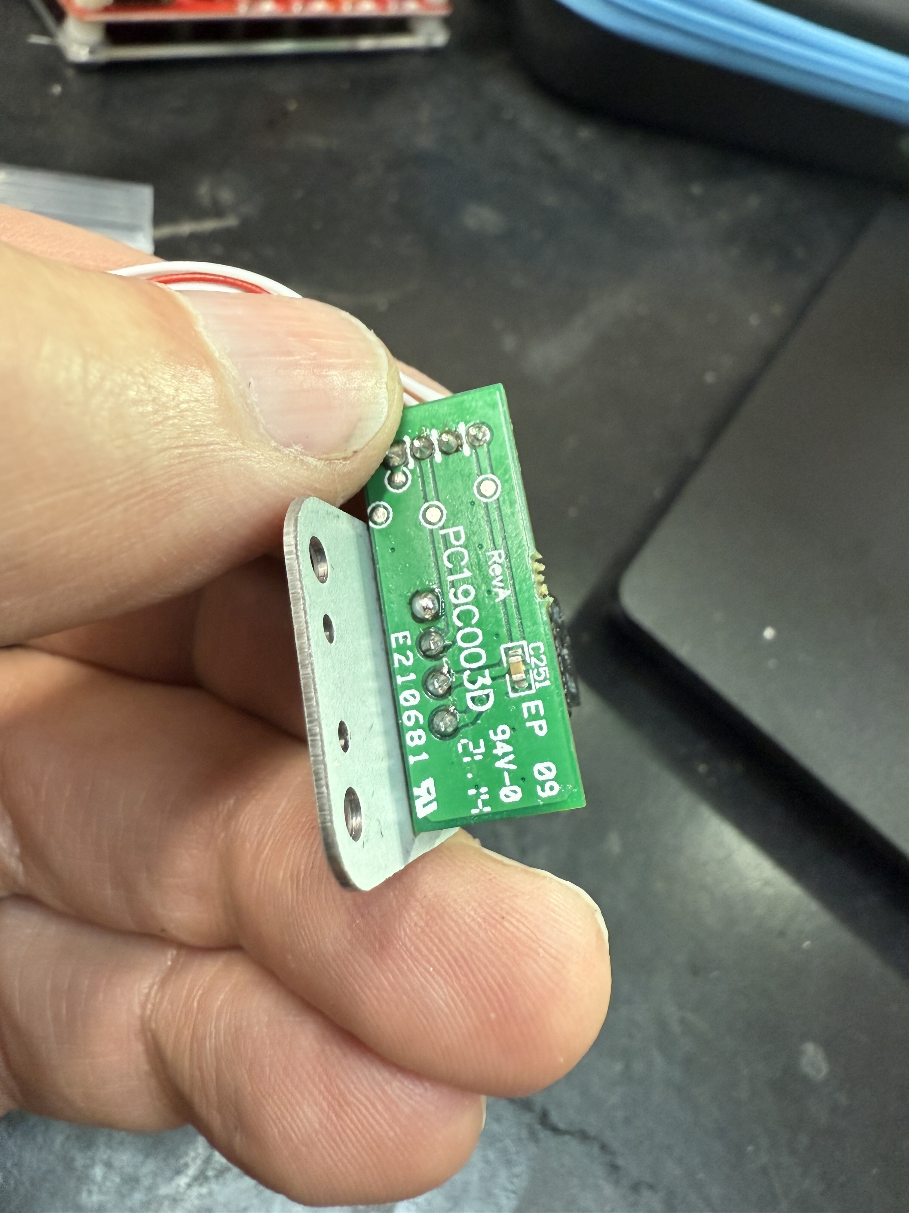
So i study the machine and carefully disassembled the thing. And found the problem. The jog wheel sensor wasn’t weld and barely touch the connector. Everything solve after i solder it.

So i take a moment to detail the disassembly.

Step1:

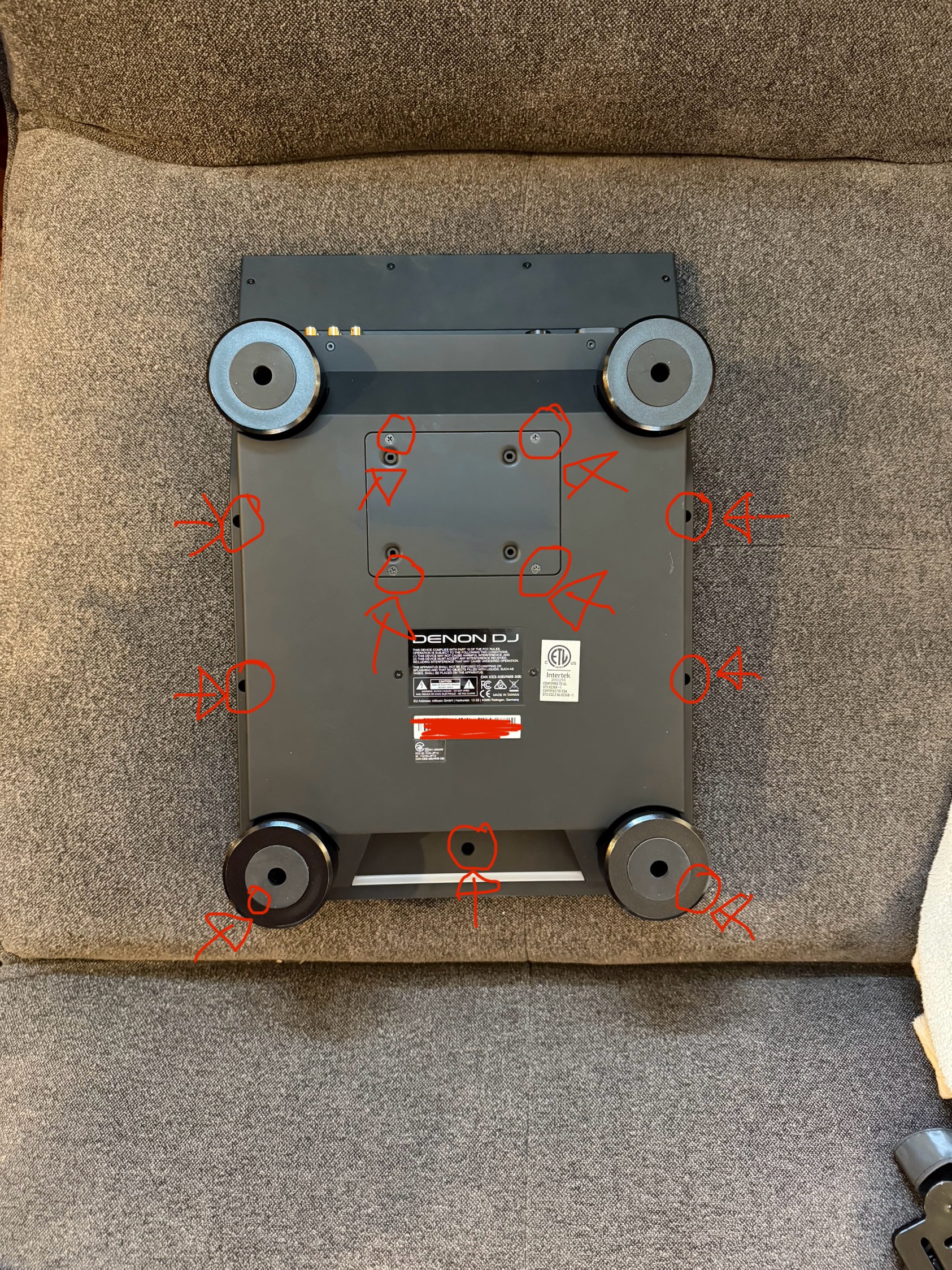
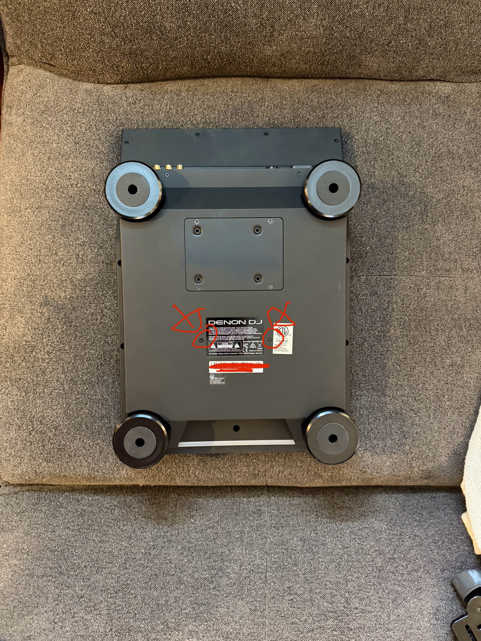
With a star screwdriver, remove the 4 screws from the hard drive plate.

And remove 7 screws all around:

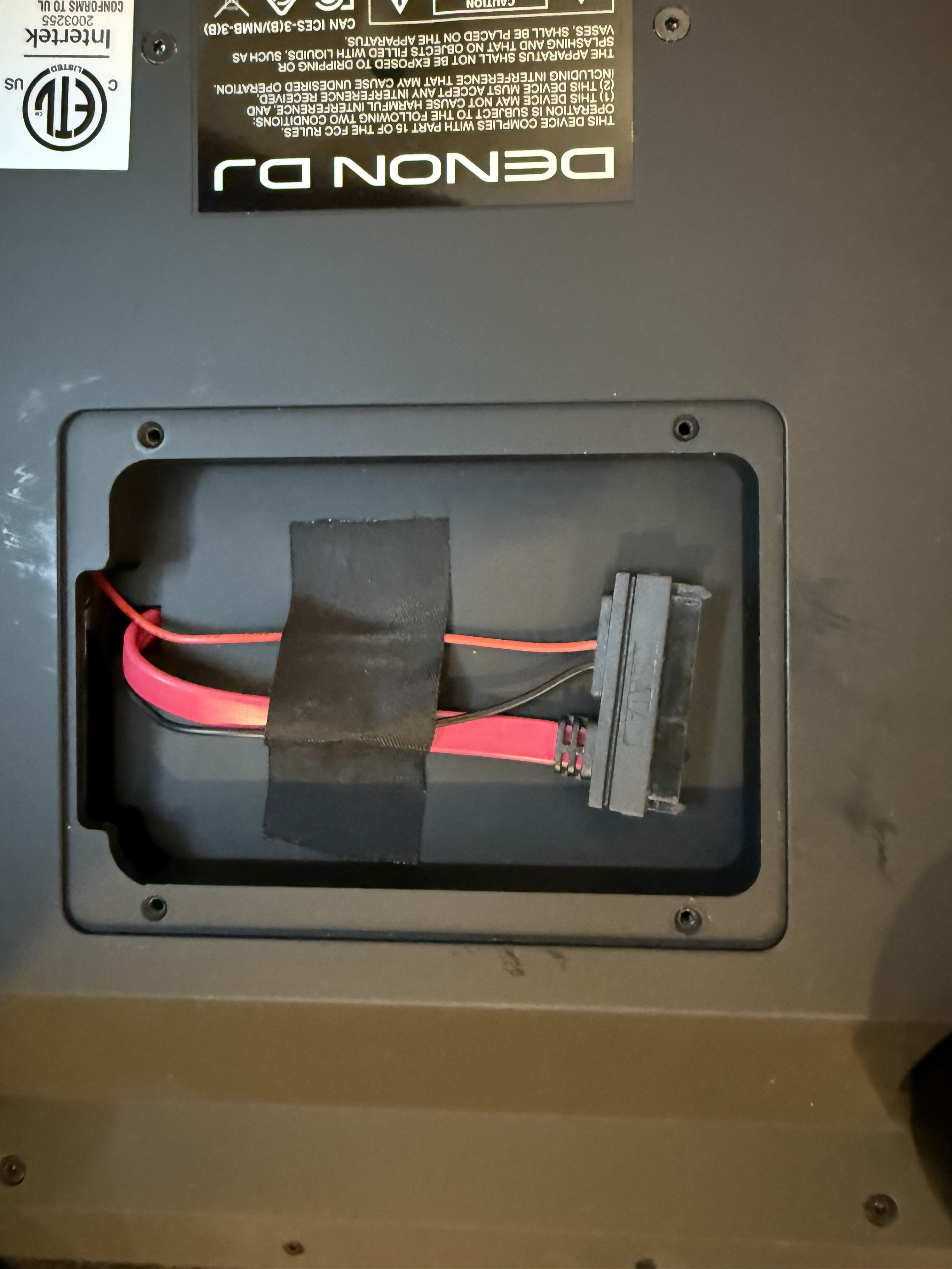
Step 2 Remove the tape in the hard disk area to free up the cable

Step 3

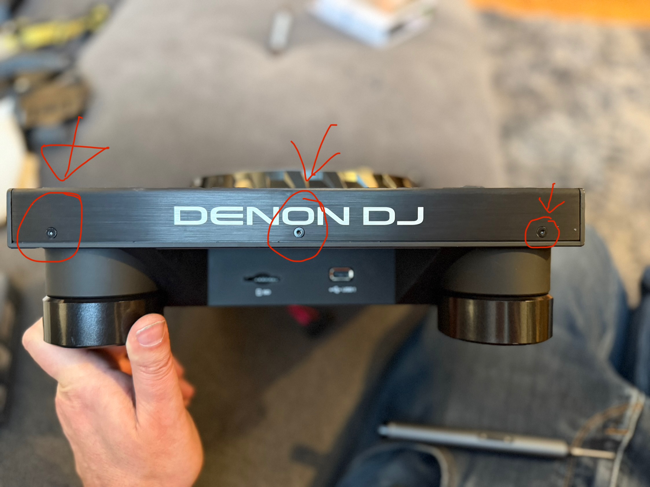
With a allen srew driver. Remove the 3 screws on the top of the Denon SC6000:

Step 4 Remove the 3 screws from the face of the Denon.

Step 5

Remove the srews from the bottom. Caution to the length of them they are different from the top and face.
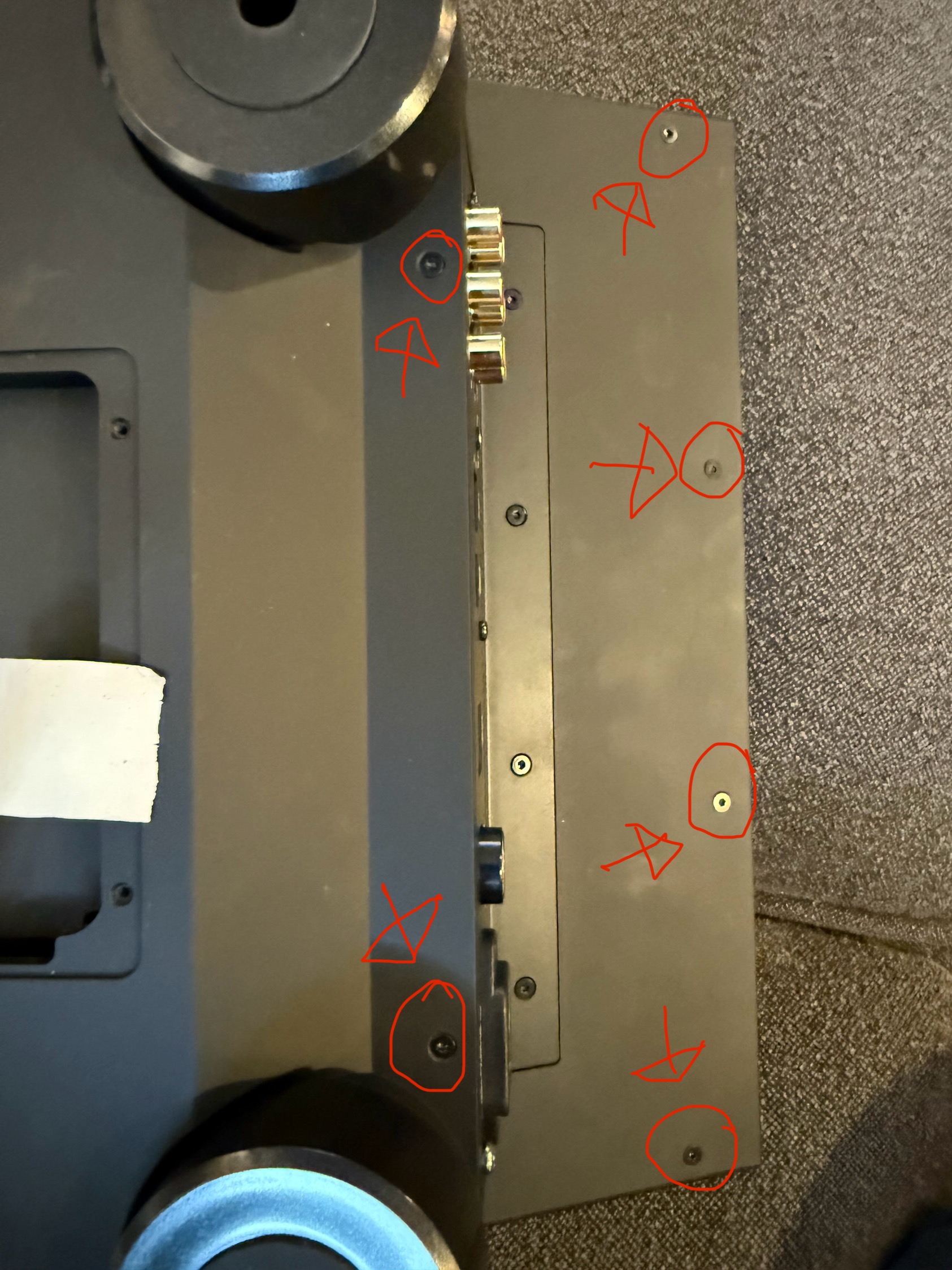
Step 6

Remove 2 screws each side of the sticker. They are metric screws. Remember.

Step 7

By the table feets, trow the cover. It will slide a bit to the front to clear the usb and card connections.

Pass the hard disk cable in the hole. Voila the machine are open

You want some more?

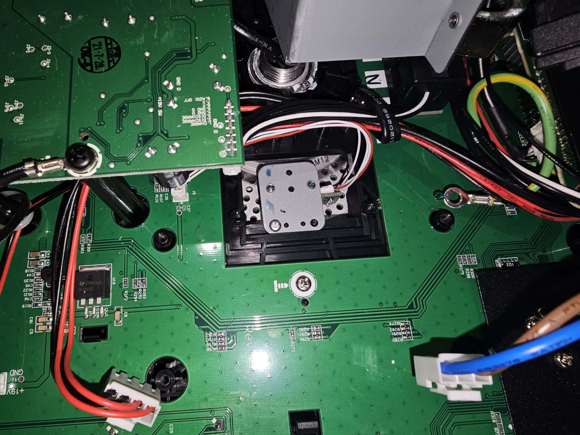
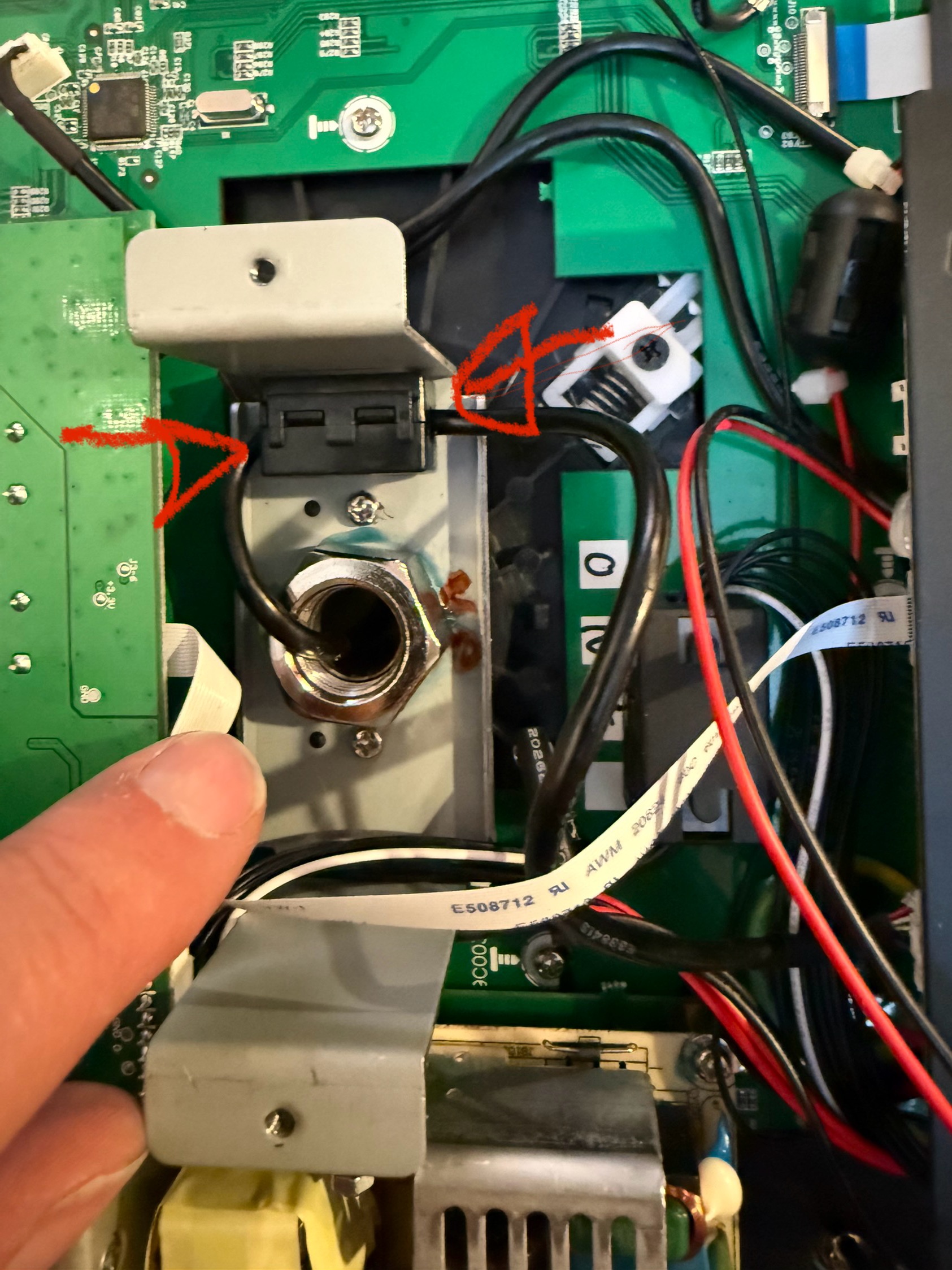
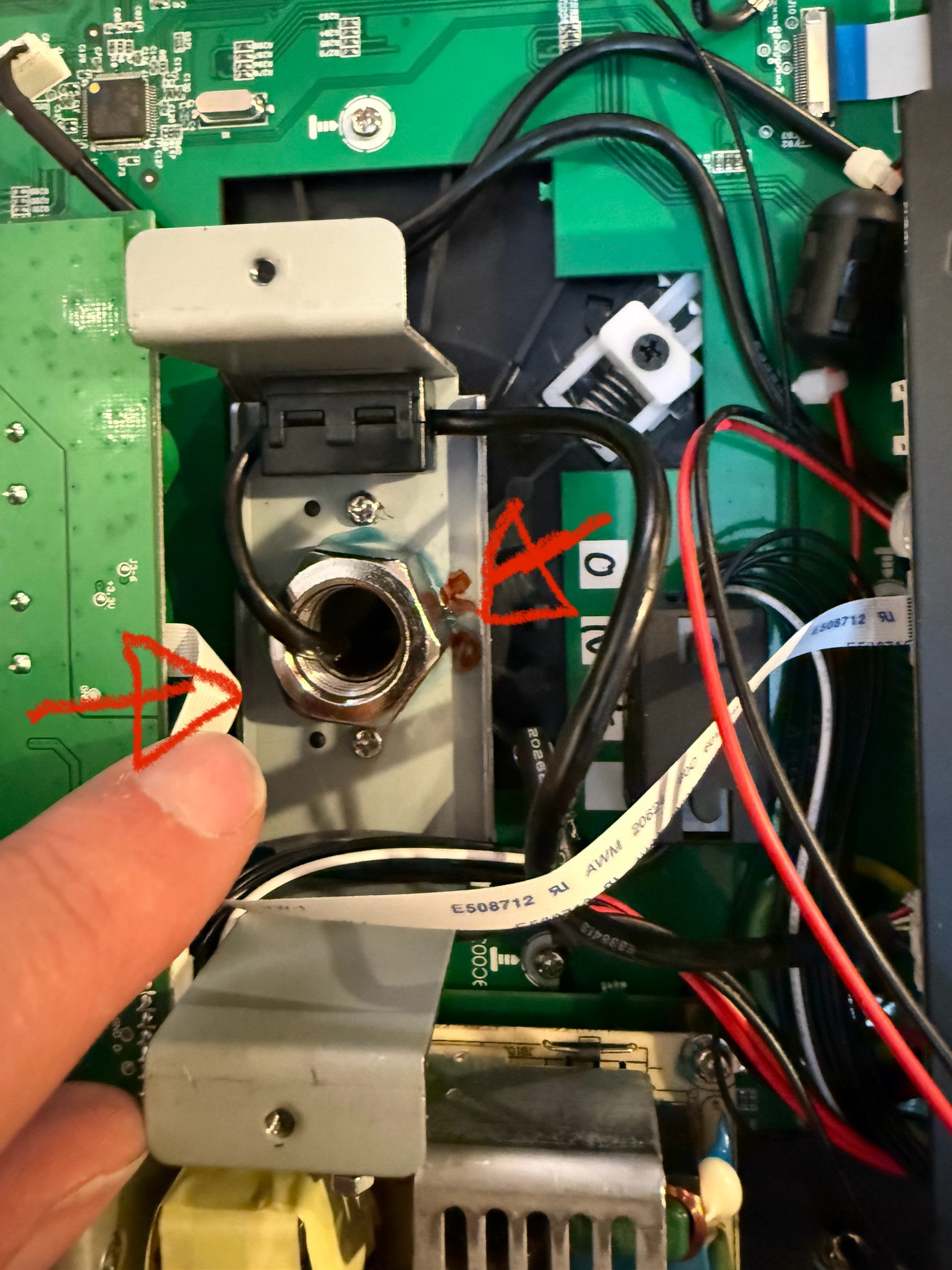
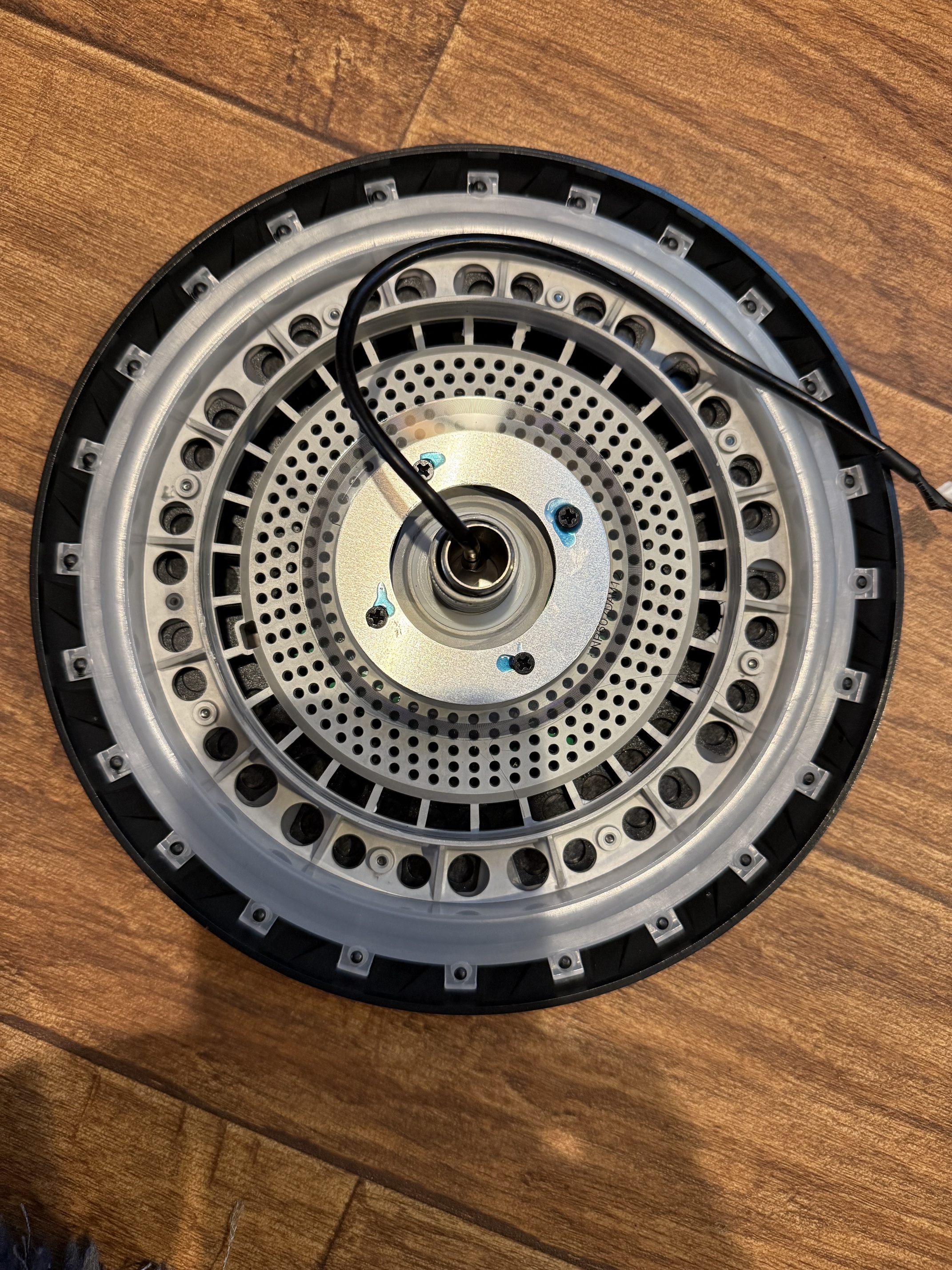
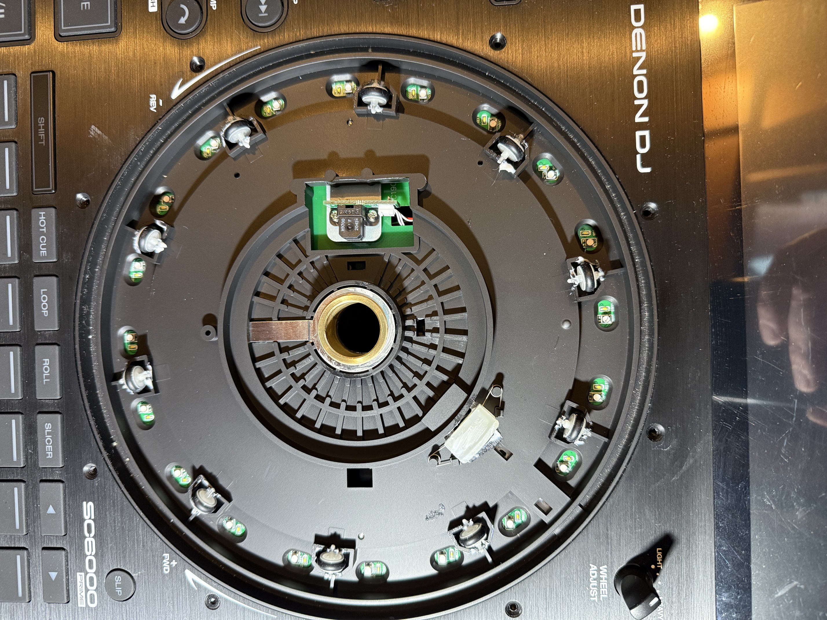
Here the way to disassemble the plater. Under the motherboard. Disconnect the cable with a small screw driver.

Now, unclip the black square thing to free up the black cable.

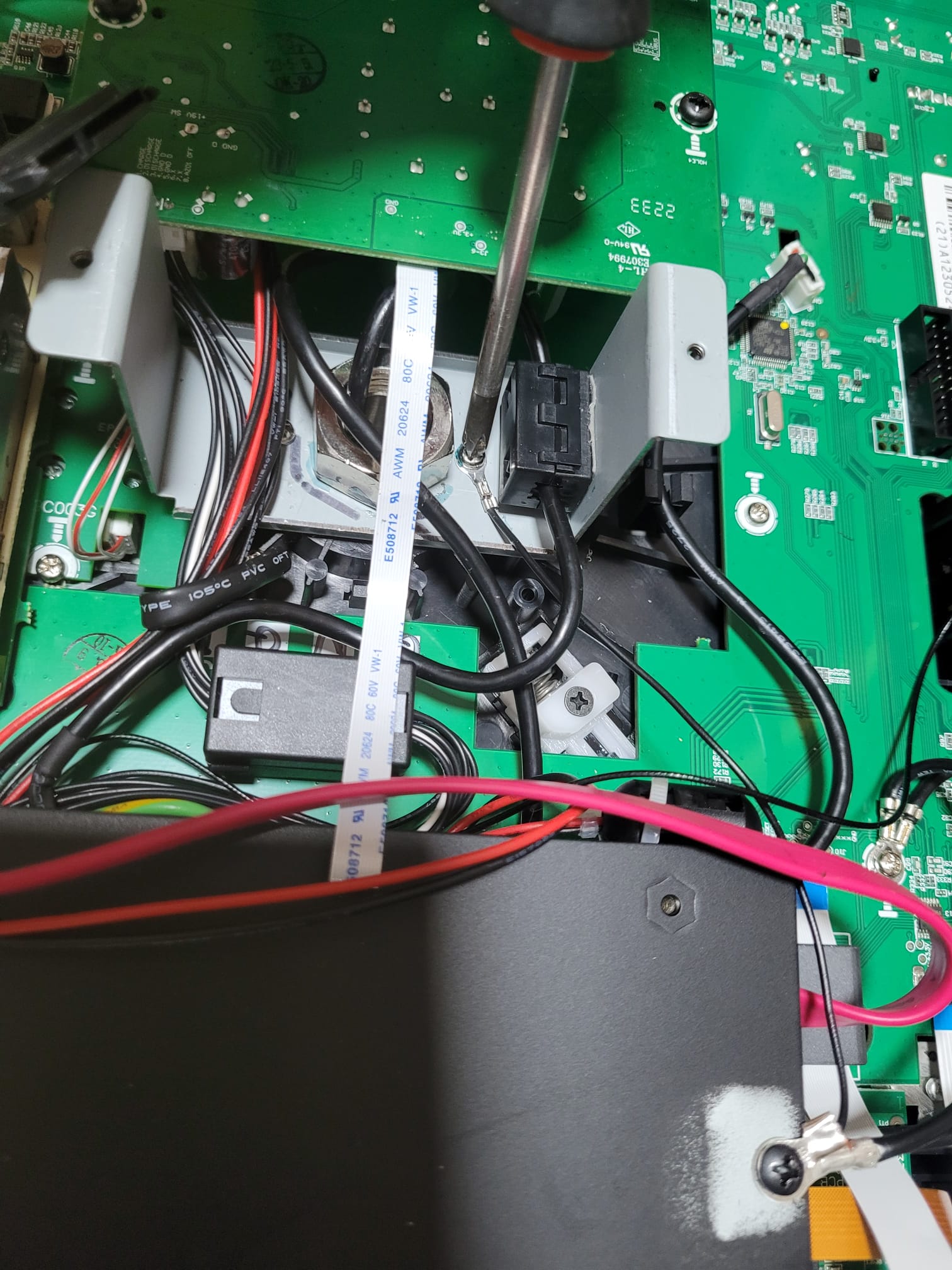
With a key, remove the big nut. It stick with locktite so need a bit of force.

Note i make a mark to identity the up and down. Very important if you don’t want a reverse screen😉.

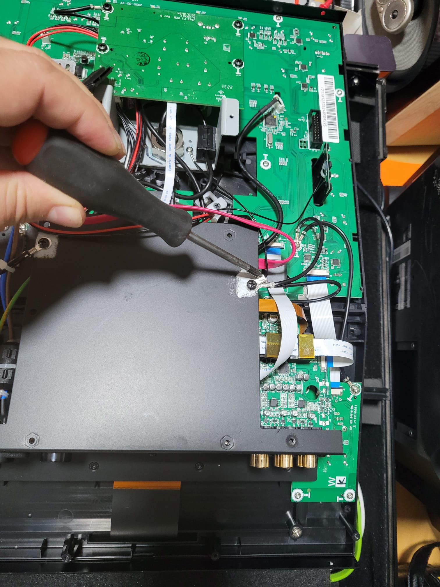
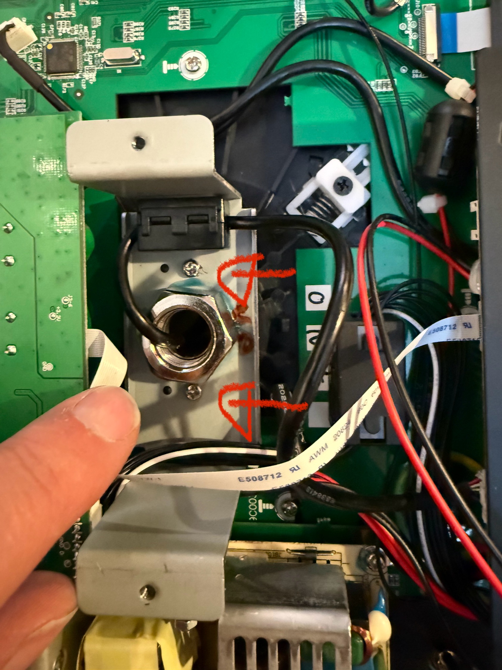
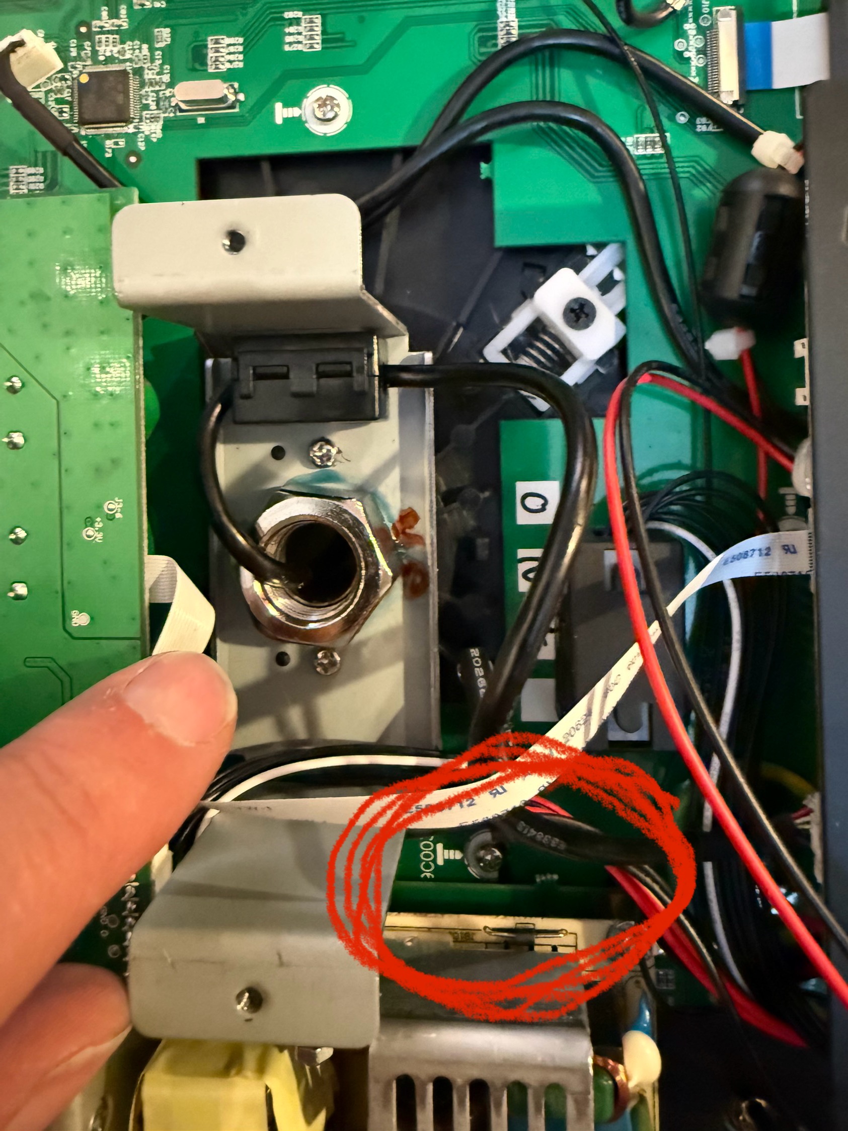
Remove the 2 screws and carefully remove the metal plate. Be careful with the cable around.

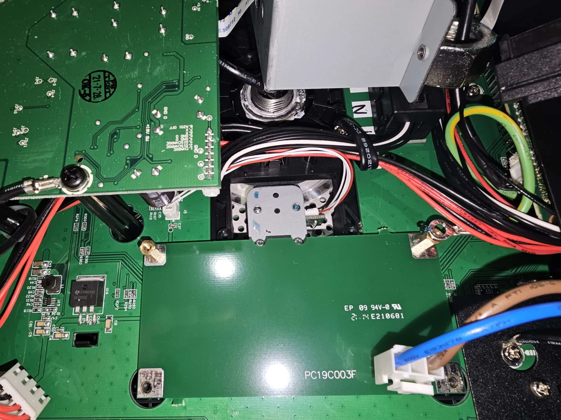
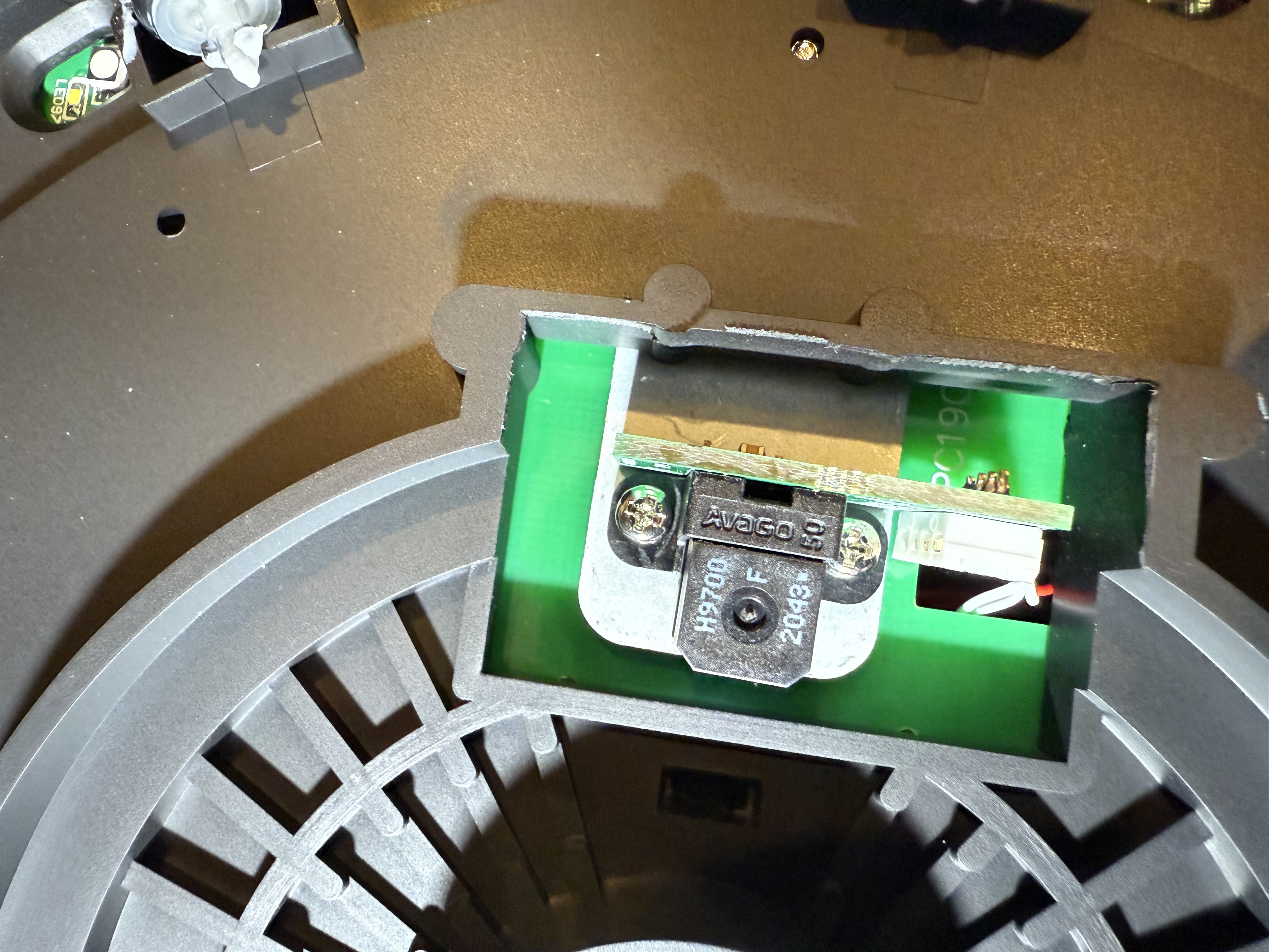
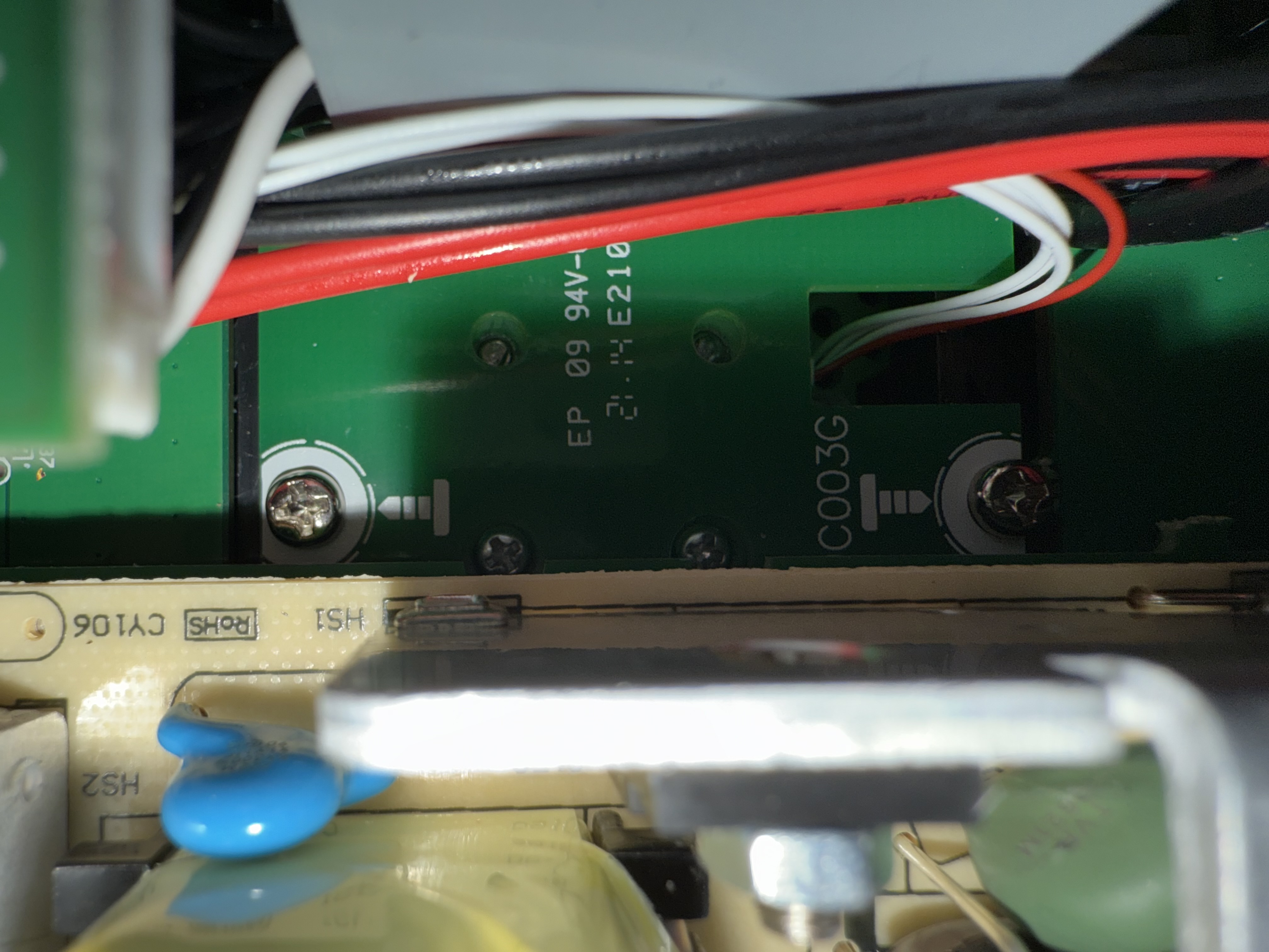
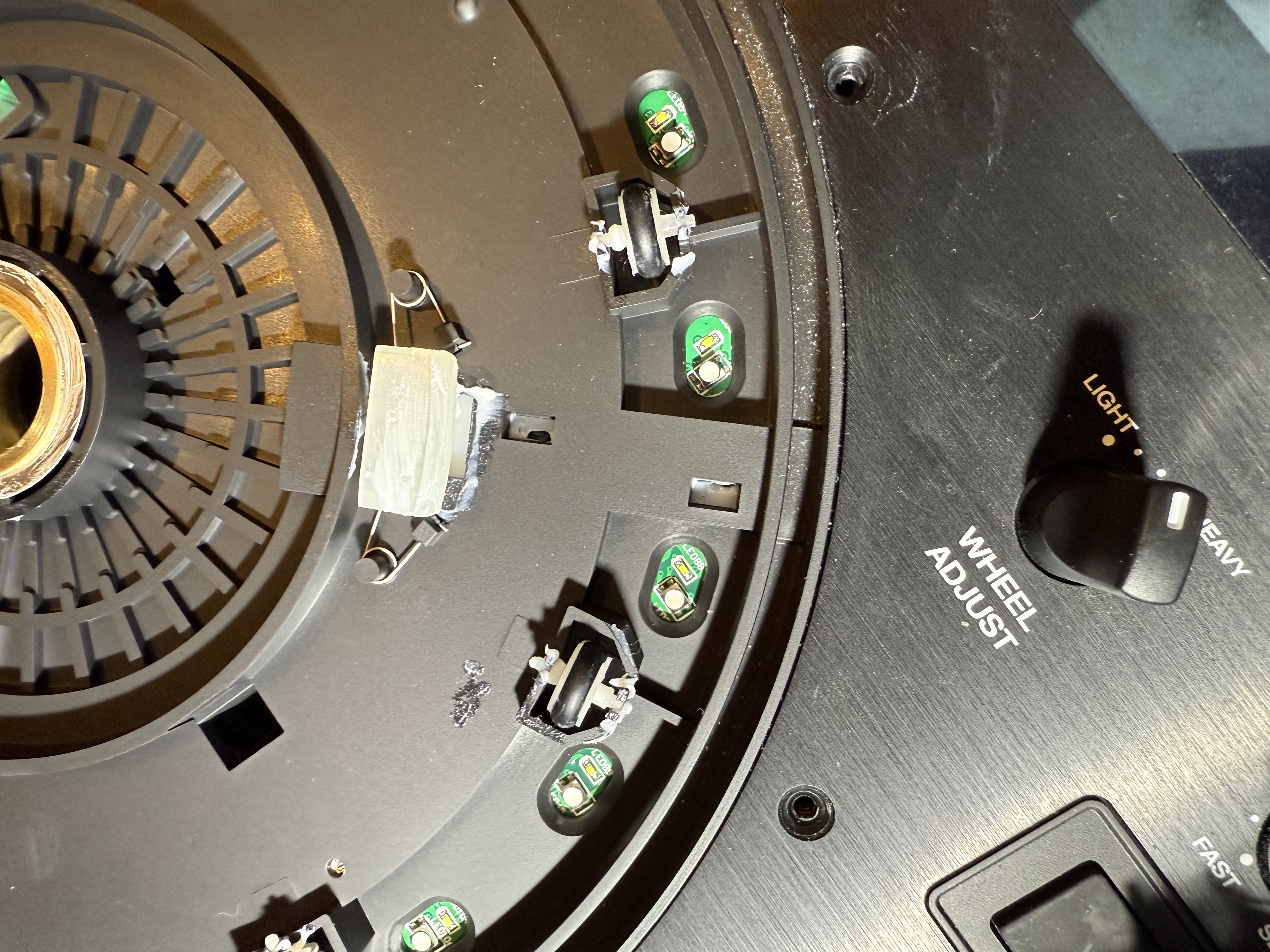
After you remove the metal plate, on the left side of the table( you right because the table are flip) you will see a green board without electronics. Just bellow the yellow board Here:

Remove the two screws

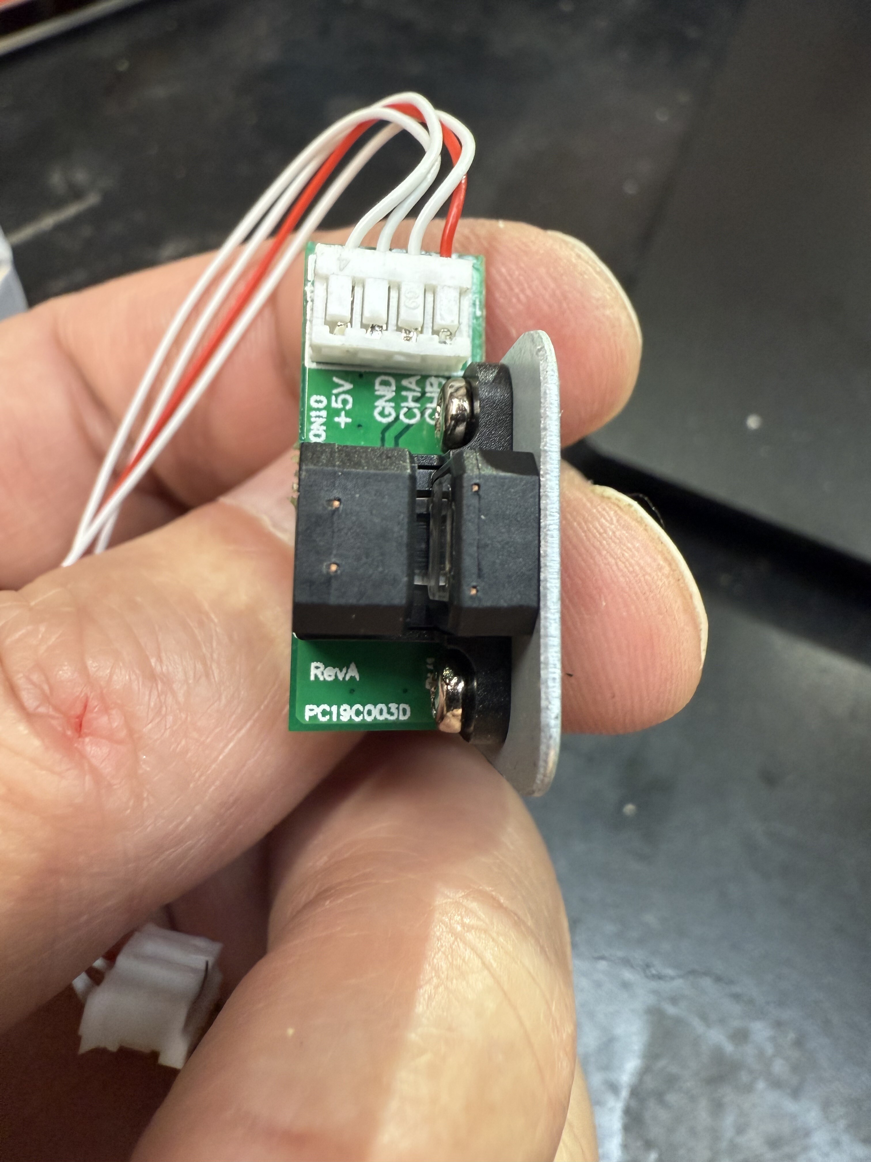
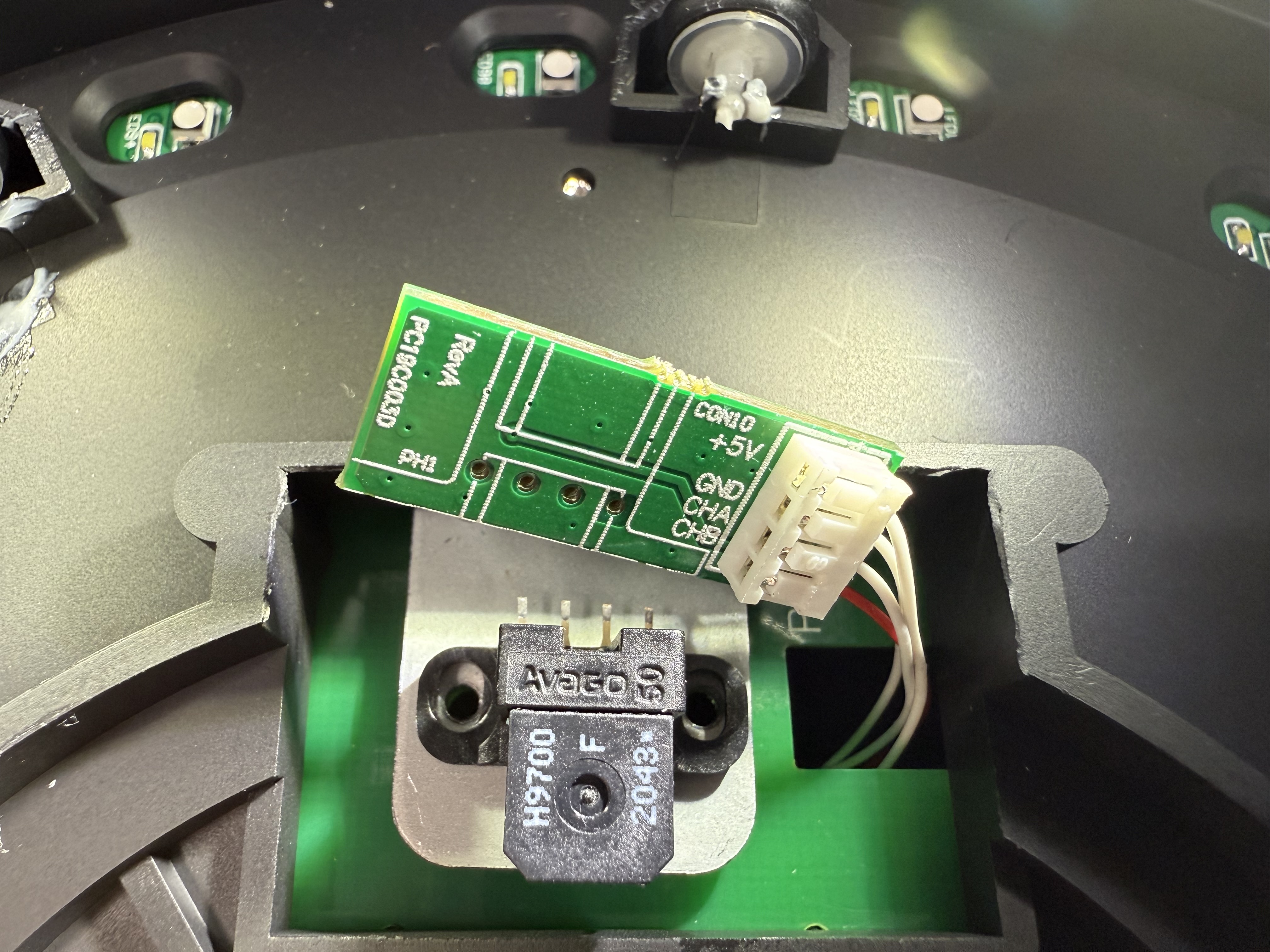
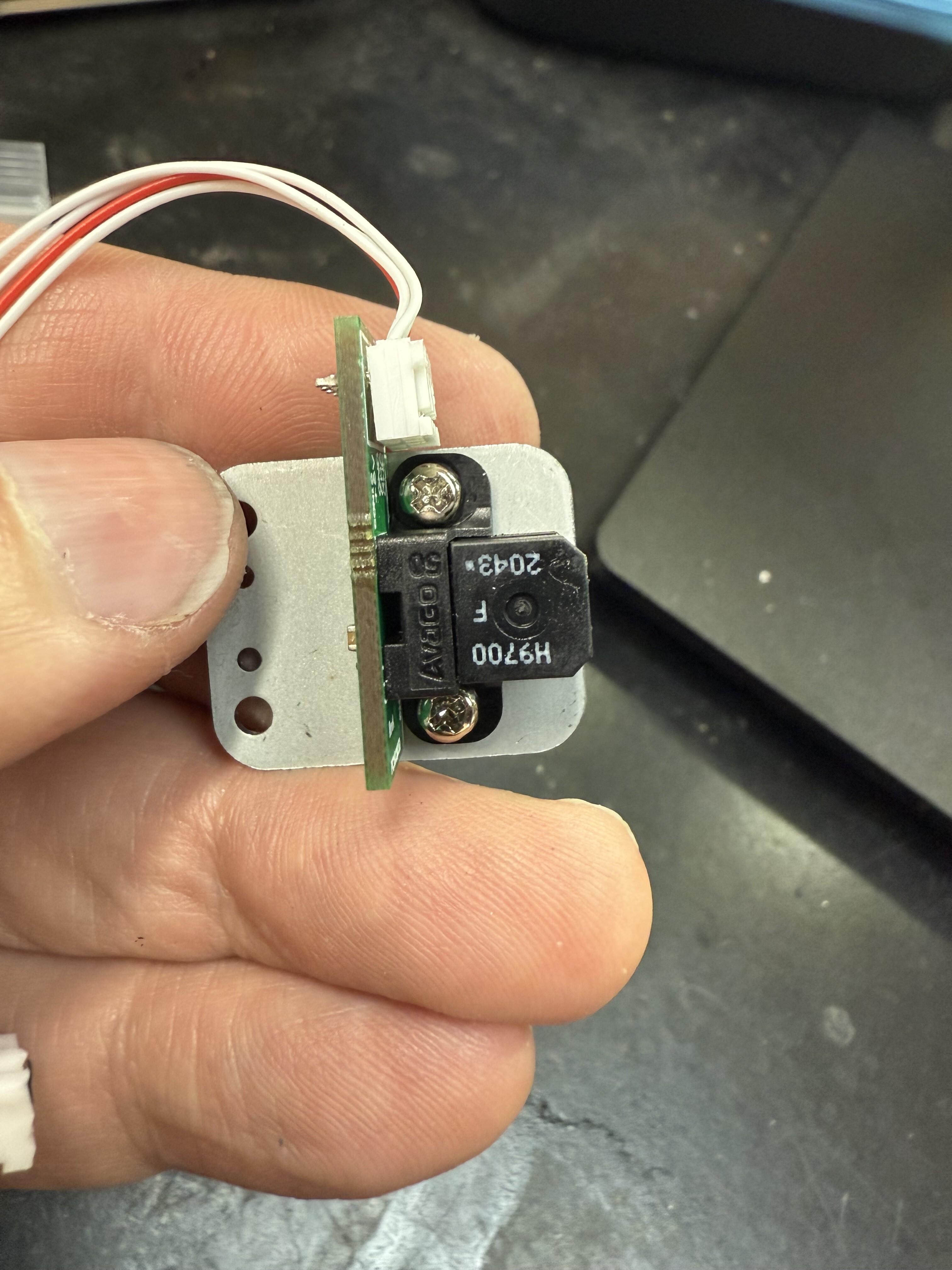
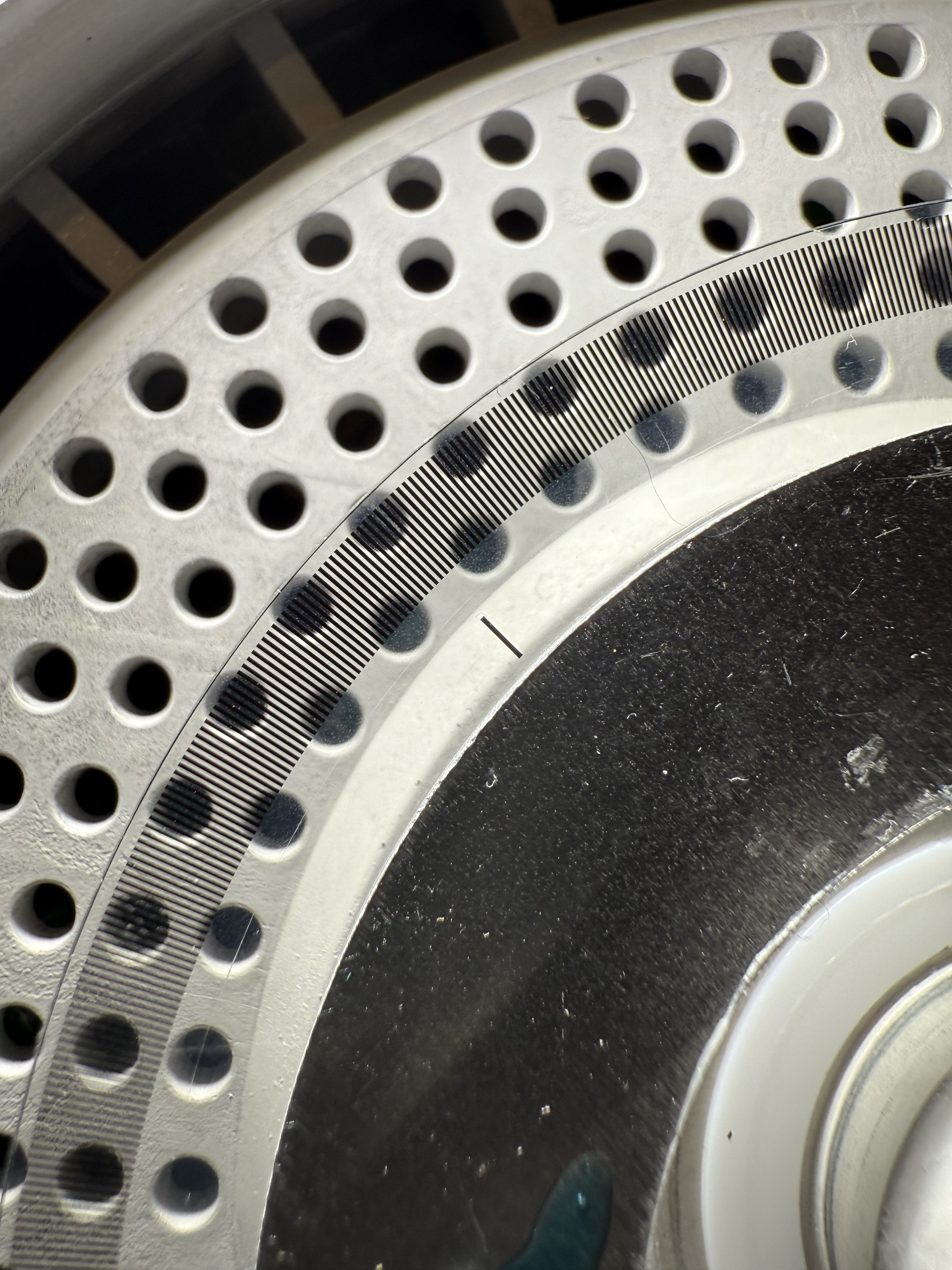
Under this you have the metal plate holder for the jog wheel sensor. Remove the 2 screws and carefully remove the sensor without damaging the sensor disc. Sorry i forgot to take a picture but i give you one from the other side to understand .you will free up the sensor. Disconnect it from the board

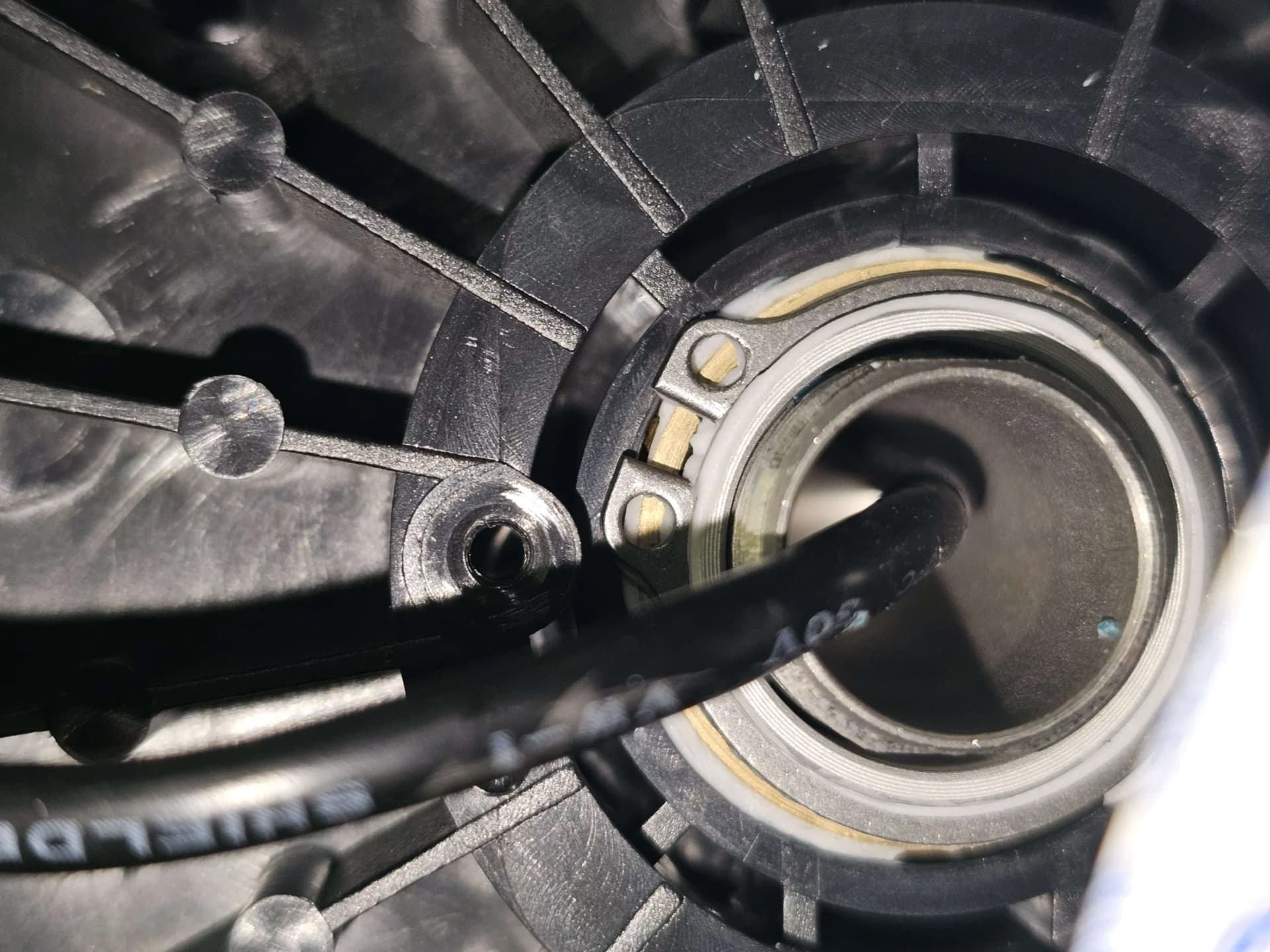
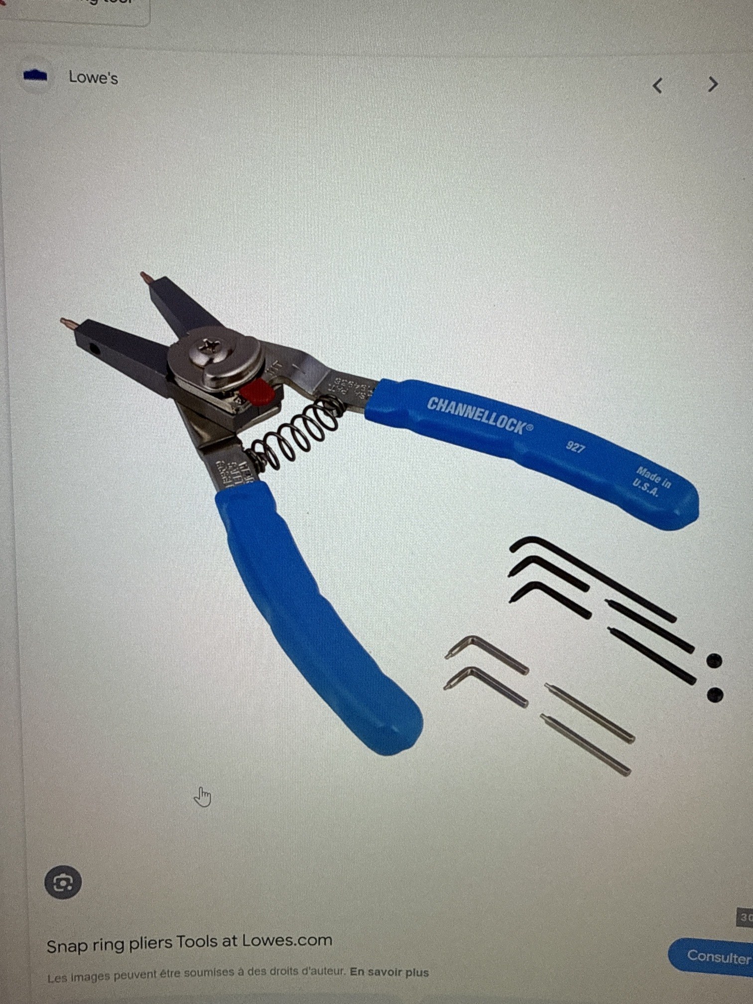
Ok now the serious thing🤣. On the big shaft where you remove the nut. You will find a locker ring. You need a tool to remove this kind of ring . it’s a ring pliers.

After you remover the ring, the plater are free to remove. Take care of the sensor disc

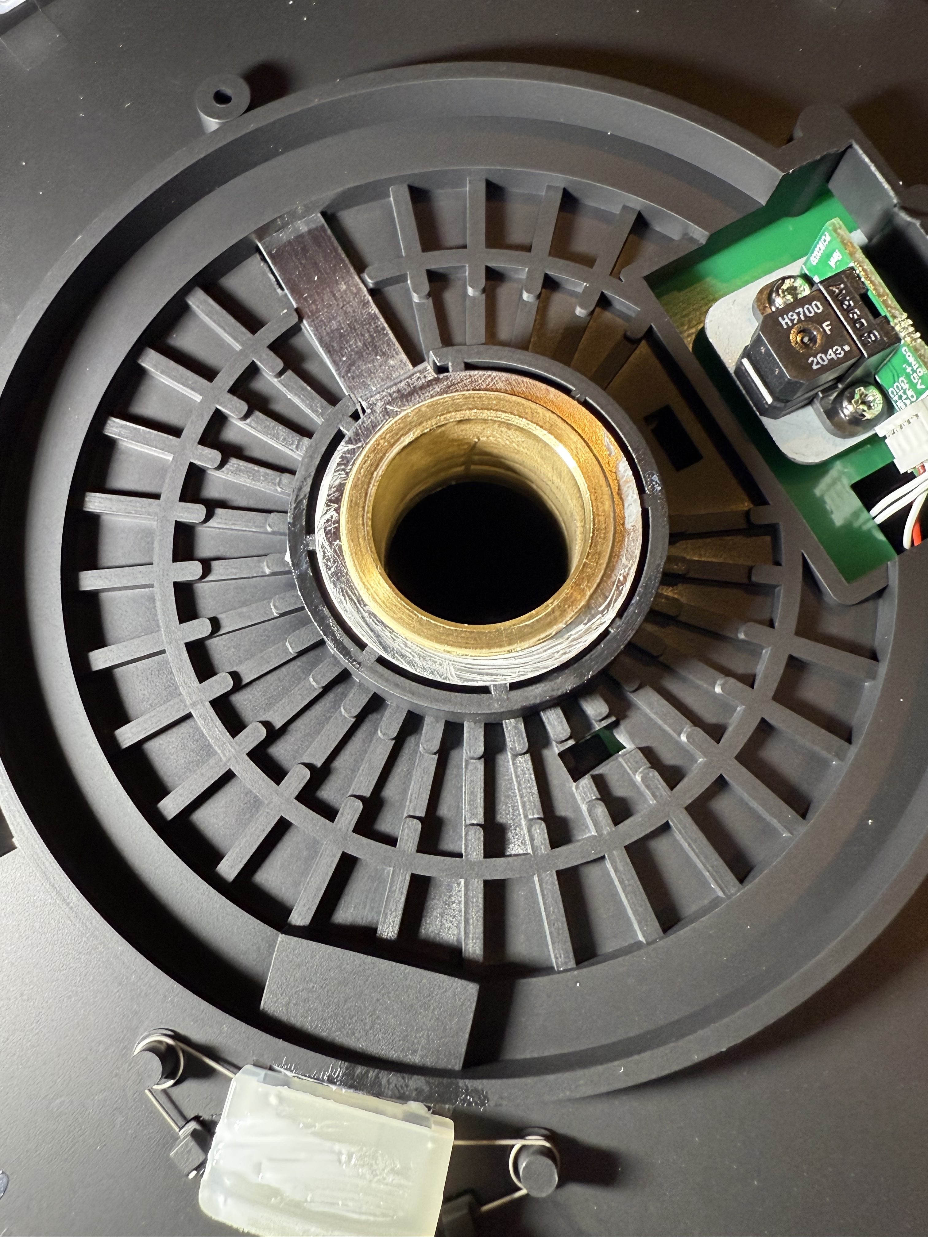
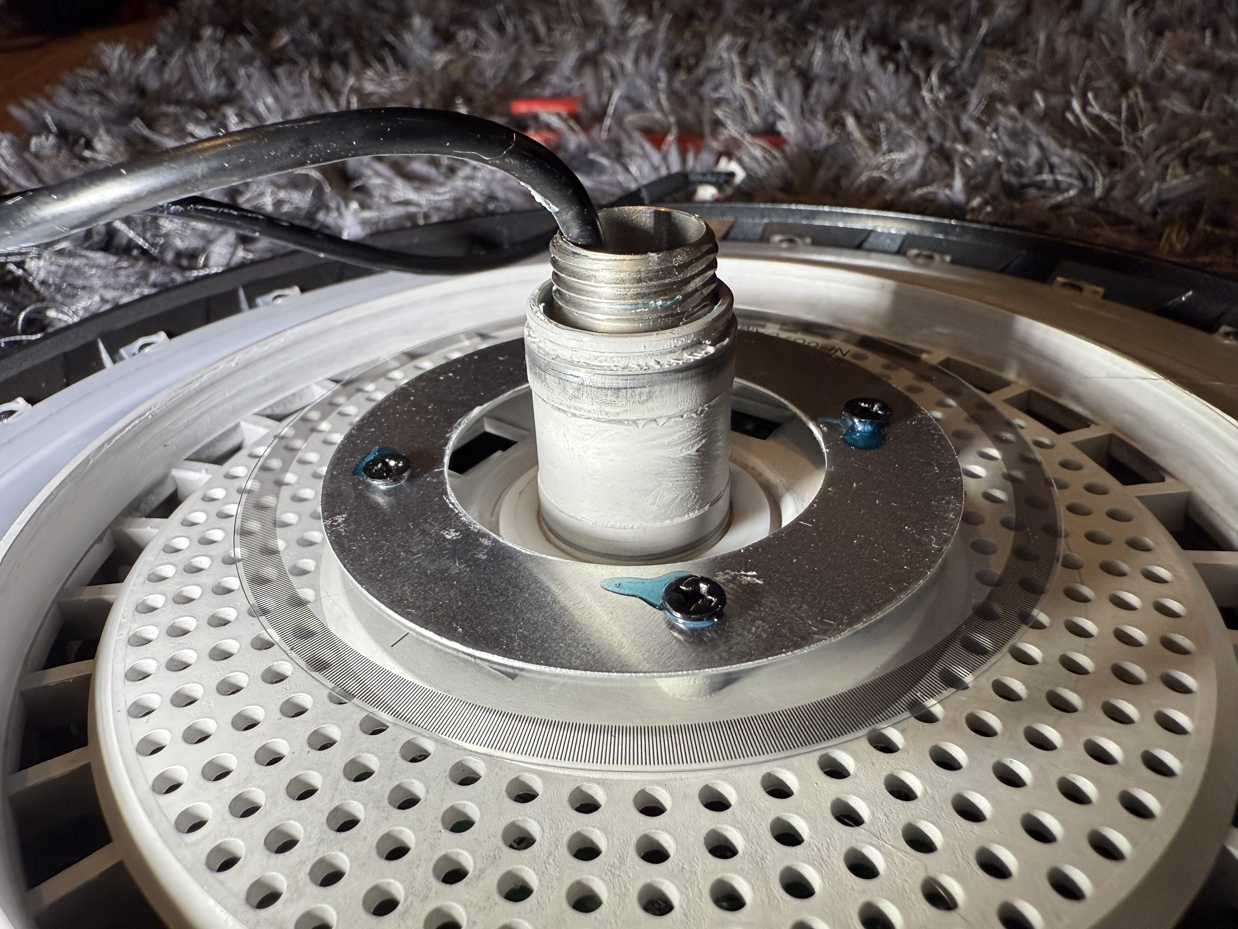
Clean everything as new. I clean the shaft, the bushings , and the break with isopropyl alcohol.careful with the disc.

I use lithium grease on the shaft, the bushing and the brake. Also on the pivot on each wheel.

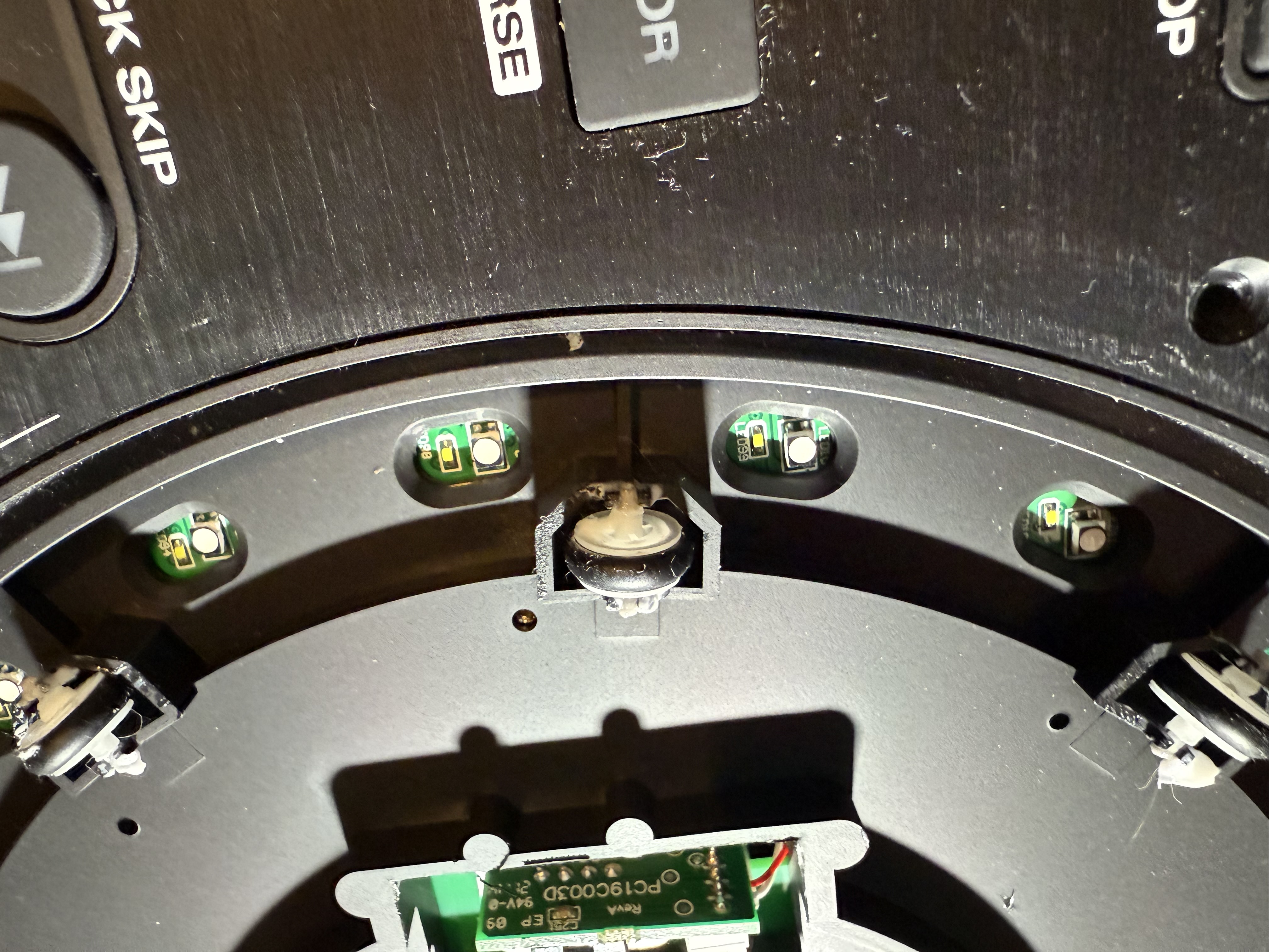
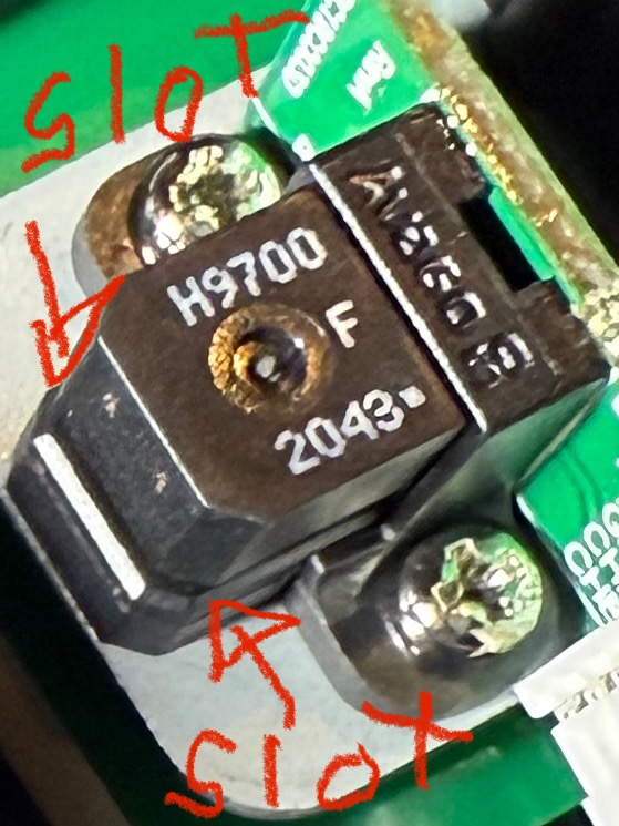
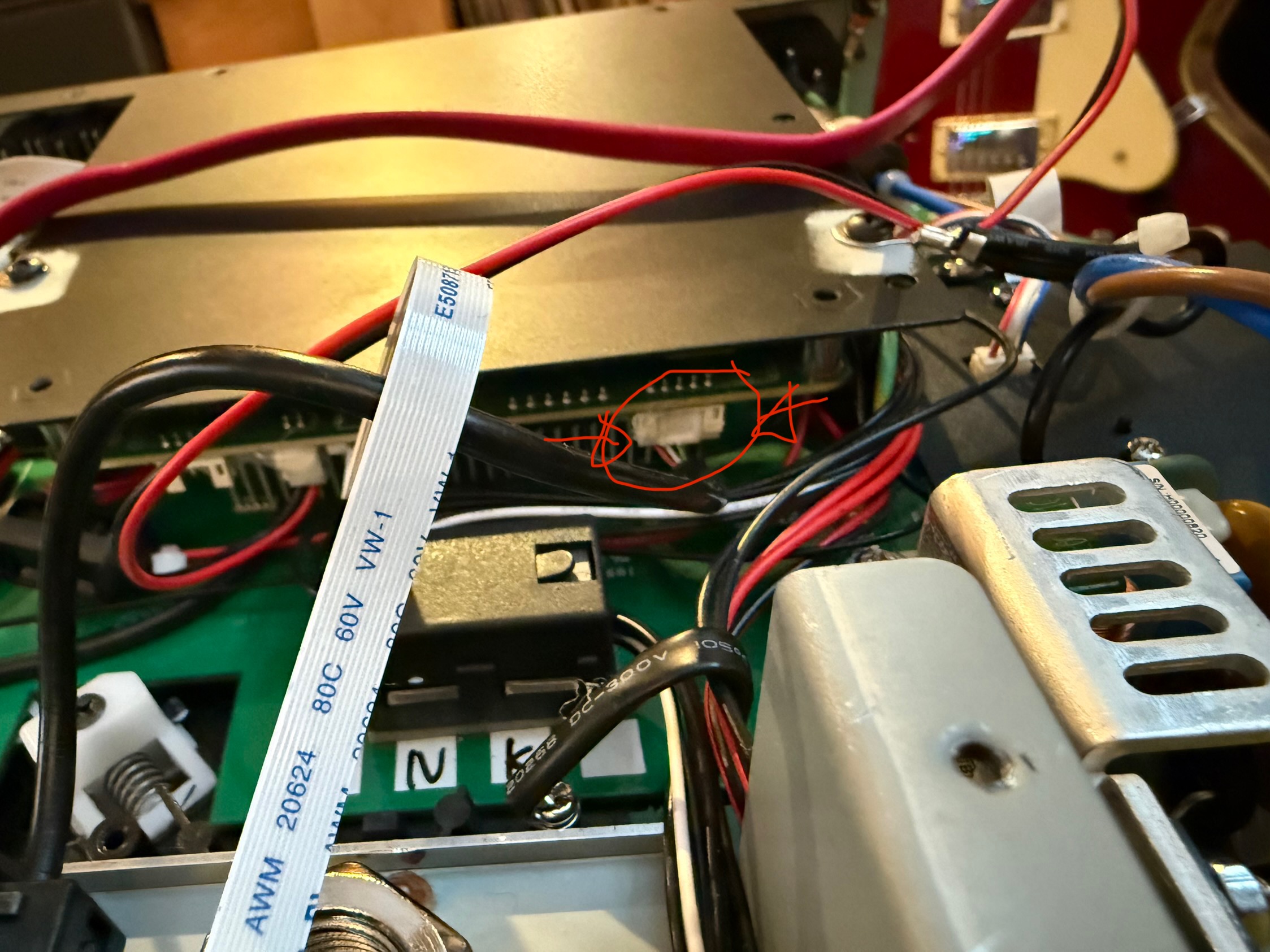
Check the weld on the sensor. It was my problem :wink:

Now reassemble. Congrat, your table will work better than ever. The plater are smoot like a real one. The brake come back like new. No more rubbing sounds or loose plater. The original grease was a ■■■■!

Cheers

12 Likes

Great work !

1 Like

That deserves a beer! Well done :clap:

1 Like

Bruh! For your first post in this forum this is awesome!! Thank you! Would it be OK with you if I put this info in a github repo with attribution to you and this post?

I am considering modding an SC6000M soon. There is a ton I am going to need to learn :rofl:

1 Like

Yeah no problem! Thanks for your comment

1 Like

Thank you for this breakdown. Any chance do you know if this breaking this down and cleaning it would resolve the infamous grinding on these jog wheels too? Some players spin smooth and some just grind to a quick stop.

Absolutely. The grinding noise are the shaft friction on the brass bushing. Clean the old dried grease and put lithium grease. Will spin as new table.

Many thanks.

This guide is pretty on point so far. I have just about finished one deck. Here is an image of the retainer clip that you need the ring pliers for. Also the large nut is pretty large indeed but was not horrible to remove. I had to improvise since I did not have a wrench large enough but managed. If I am successful with getting this one back together, I will make a video of the breakdown to go along with the images in this thread.

Thank you again for posting this, it was a huge help indeed.

1 Like

Philippe_dube, when you put everything back together. The clear disc that has all the mini lines on it. Is that supposed to ride in between the sensor you had to solder on yours, or does it just bolt back in place? I did manage to get everything together but it does not detect any nudging at all. It spins way better, but I either broke it or I didn’t seat it back together correctly. My only thought was that it needed to be between sensors.

Thanks for any insight you are able to share.

The disc with mini lines is the encoder. If it’s not between the sensors - they will not detect its rotation.

1 Like

The sensor need to be removed before you remove the platter. And when you put back the platter, you put back the sensor but take care to fit the sensor disk between the two sides of the sensor. In the slot.

1 Like

Yes this is a big nut. :wink: don’t forget to note the placement of the tread. Put a mark. Or your screen will not be exactly in position when you will rebuild it.:squinting_face_with_tongue:

Thank you. I thought this might be the problem. Hopefully I didn’t bork it.

I already experienced the upside-down LCD. still trying to get it perfectly centered again now that its right side up. I ended up marking the metal bracket, not realizing my mistake till after the platter was already removed.

Great success!!. I took it a step further as I found that removing this section on the side made accessing the sensor and putting that metal bracket back in place exponentially easier to deal with. To do this you just need to remove the 4 screws on the top. Disconnect the 2 clipped connection and there was a zip tie I had to cut. Once you remove the top part there are 4 stand offs that you can unscrew and remove the bottom PCB which looks to be blank. Here is what the area looks like with the section removed. I also suspect that if we remove the portion that contains the USB and SD card reader and flip it up out of the way, it would make working around the ribbon cable that is in the way much easier too. That looks like just 4 screws holding it in. I still need to do the other deck and with that one I will try to video the entire process. This thing spins better than when it was new and zero sound doing so. Huge thanks to you all.