I replaced the cue button, and after assembling the remote, when I turned it on, there was a short circuit, and the indicator light turned on. Can you please advise me on what I might have done wrong?
As soon as the monitor lights up and the screensaver appears, the indicator light turns on and the screen goes black, and then the cycle repeats. This didn’t happen before I replaced the button.
As the official stance on here is to send any equipment to an authorised repair centre, I can see there will be very little to no help from most members of the forum.
I can see that you’re from a place where Denon DJ may not have an official service centre so it makes repairs harder.
I don’t think you’ll find many people that can help but sometimes they come along. It’s hard to tell from the photos and description as it could be anything that has caused it.
The community can help with some maintenance but it’s not official. The SC5000M platter issue was one of them.
I wish you well but there are too many variables here.
This would be virtually impossible for someone to diagnose unless they had the boards in front of them with some test equipment.
The best advice is to get it to an electronics engineer if no Denon repair centers exist in your location for them to diagnose it for you, hopefully it will only be something simple as a cap, fuse or mosfet.
Best of luck with it and i hope you get it sorted.
This might be as simple as just not being re-assembled completely & correctly. A connector may not have been fully plugged back in, or one that you didn’t even mess with might have become disconnected. Assuming the solder job was done correctly on the button, and that’s certainly worth checking, I’d disassemble and reassemble everything again carefully. Double check every connector, even ones you didn’t alter. Hopefully this temporary malfunction is a designed-in attribute when something is amiss rather than causing further damage and can be fully restored without additional repair.
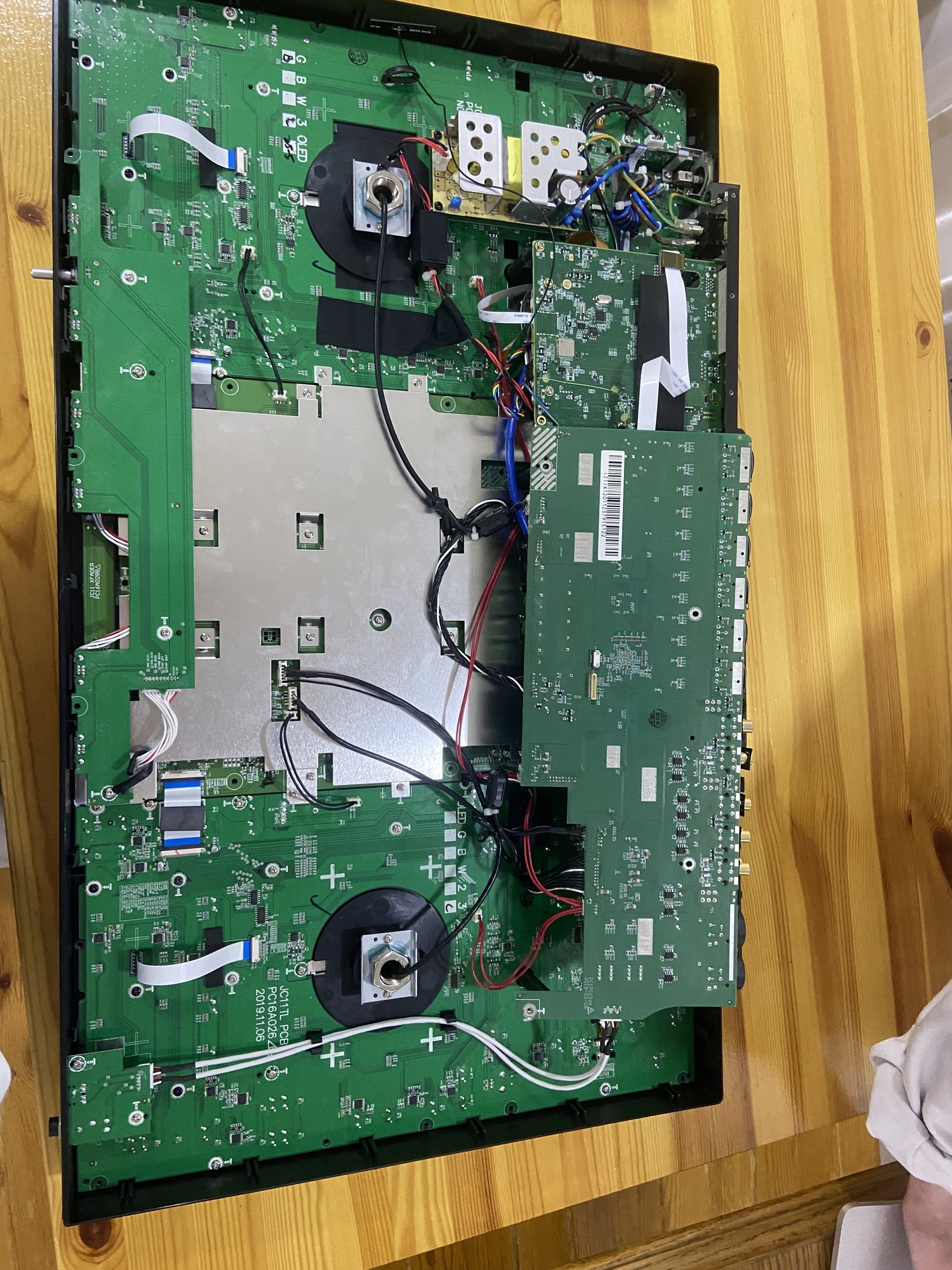
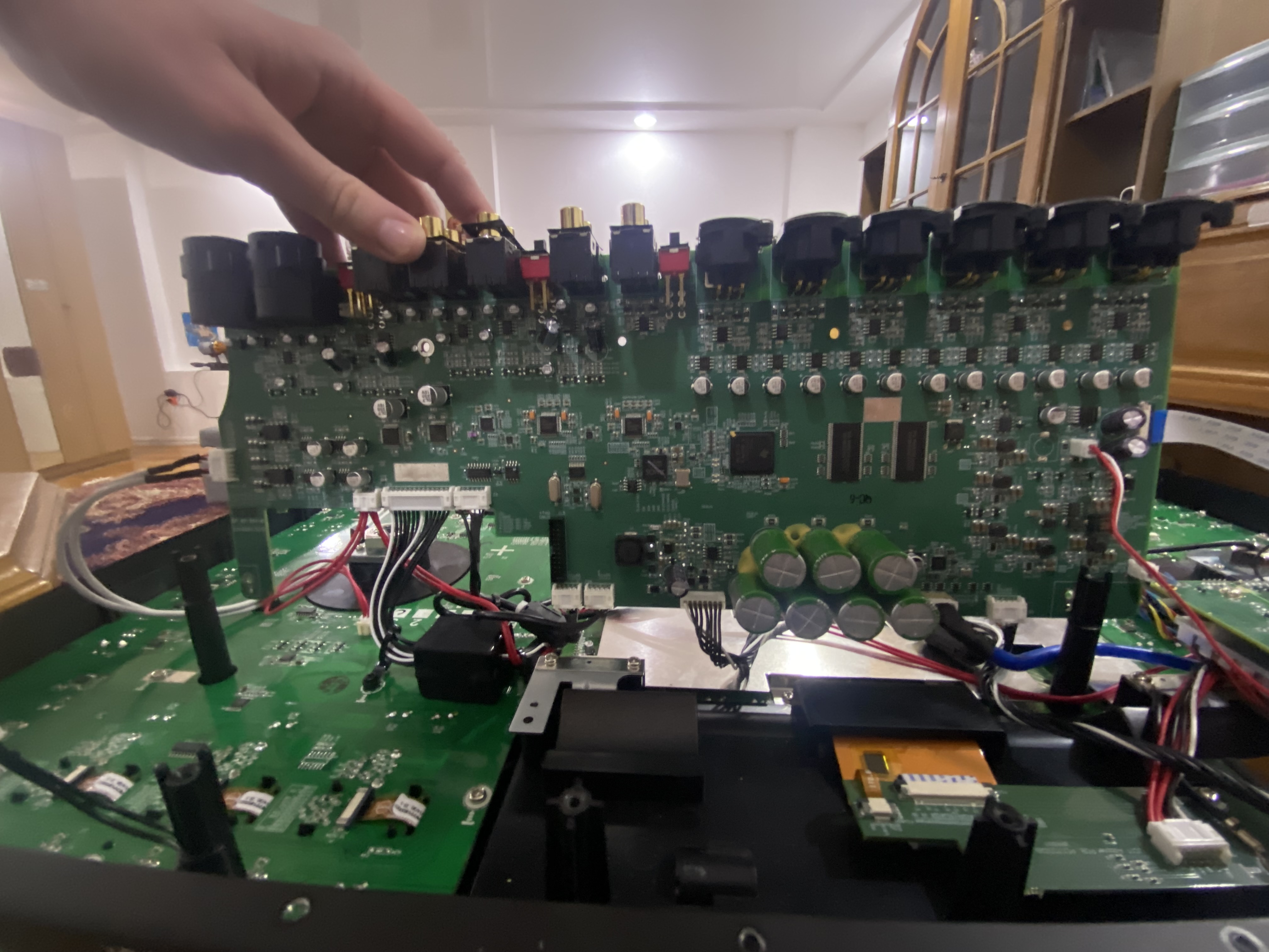
Can you post a photo of the actual cue button replaced? Your pictures don’t show that. Your second photo shows a hazardous arrangement with live pins covered in green tape. Don’t leave that out where there are kids, pets or goldfish.
I’m guessing pictures 1 and 3 were the ones you took first to reference which connector goes where. Smart thinking.
The first thing I would try is removing your newly replaced cue button and using some solder braid to clean up any excess, then powering up again. How many pins does your cue switch have? Got a part number for it?
I simply covered the button with plastic, there was no physical intervention on the board. In other words, I disassembled and reassembled the remote control.
I’d suggest getting it into an authorised InMusic service centre - definitely not any ol’ 3rd party repair hack (any non-authorised service centre)
Some of the primes need specialty kit to get into properly and a certain amount of savvy which won’t necessarily be present elsewhere.
That said, there’s two counterpoints here:
I would like to see the ultimate progression and fruition of some peoples ideas, that every fader and every “easily stabbed aggressively” button is user changeable from the top of the deck/mixer.
Along with that idea however is the fact that such “modular” design COSTS ! And it costs in more ways than one.
A fader which is soldered direct to PCB is a pain to access, a pain to replace etc but solder connections tend to stay solid and true for decades if they’re done right in the first place and not subject to drinks spills or salty corrosive sea-air etc: It’s connected by 4,solder connections from fader to pcb.
A fader which is mounted somewhere and has a little 2, 3 or 4 pin molex type connector is solid enough in itself, but the connector gives it a massive uplift in mtbf (chances of going wrong). A fader with a tail of 4 wires coming from it into a plastic 4 pin plug has 4 connections leaving the fader …. 4 connections into that plastic plug… then on the mixer/deck etc side of things there’s 4 connections from the 4,pin plastic plug, leading to 4 points on the PCB - that’s 16 points of potential failure.
Which is better 4 connections of which any one could cause the fader to stop working as intended ? Or any one of 16 connections failing causing instant issues?