Music visualization technology in real time (RTMV technology)

This is exactly what we need to make light shows that adapt to the rhythm of the music in real time (like the youtube link I showed you in my previous post).

So if I understand point number 5 correctly, it’s possible to send different information to different light sources spread over a given space. Or will each light source react to the rhythm of the music in exactly the same way as the others?

How can your system manage and differentiate between light sources in a space? Is there an addressing system where each light source has its own address and receives part of the information assigned to it?

How can several light sources be connected to your system? in series? in parallel? what type of connection is used in this type of configuration with several light sources? dmx cables? wireless dmx?

Can your technology handle robotic projectors like movingheads? Can it handle the pan/tilt of these projectors to move a light beam in space or can it only handle the flashing of the light?

1 Like

Your questions are very relevant. But the whole point is that at the moment, only those output optical devices are available to me that I can make for myself.

And these are only point light sources, which have only one controllable parameter - this is their brightness. As a development engineer, I am familiar with the DMX protocol and know all its shortcomings and problems. I understand that all modern stage lighting fixtures are “sharpened” to work with this interface. Adding physical DMX interfaces to the device, preparing a data package for control, is not a problem for me at all. Yes, I understand that to control different light sources, you need a specific data package for control and one parameter such as brightness is simply not enough.

I see visualizations from the side of the “listener of music” and I am completely unfamiliar with what a musician, DJ, wants to have for himself.

In order to activate the controls, for example with robotic projectors, I must understand how you, as a musician, understand how this projector should behave, how it should react to some piece of music or music parameter. And only having understood what you want to realize, I can start developing an algorithm that will allow you to realize your desire.

But the problem is that for this you need to have all these devices and a higher level of technical base, which is not available to me today. I am not familiar with the control approach, with the standards that are accepted by companies that manufacture controllers for controlling stage equipment.

At the moment, I only have an idea, a theory, in which I want to show that it is possible to refuse (perhaps to some extent) the preliminary process of writing a program composition for track visuals. What is possible to implement in real time. I have created fully completed working prototypes which I believe show that it is feasible and I believe even more efficient than a human can do by hand. That even at the achieved level, it is possible to create a simple, very inexpensive, accessible to all, visualization device on them.

In the next post I will continue the description for CLUBBEST and it will be more clear to you what kind of device it is. At the end of the description, you choose what you are more interested in and as I said, I will ask you to test the prototype yourself and make up and give your opinion on what you like and what not. Having a finished device in reality, this is not at all what can be seen in the pictures and on the video, I think you will not argue with me with this.

1 Like

Continued, PART 2.

These are the basic principles by which I began to develop the device. Naturally, then a lot of parameters were added that had to be taken into account, for example, the envelope of the increase or decrease in brightness should have a certain shape. The rate of change in brightness, light sources, should depend on the genre of the piece of music, and these parameters greatly affect the perception.

Initially, it was assumed that for RTMV-technology, the output optical device (OOD) should be only a 2D screen. And I really was against the option that you now see on the video. At the beginning, I thought that it was impossible to create some kind of digestible visualization in the 1D version. But the desire to build a working prototype and the lack of solid free funds led me to a linear 1D OOD design.

At the beginning, I built visualizers, such as a signal level indicator (VU Meter), vertical and horizontal options with a set of various modes of operation that automatically switched. But it all came down to one thing, no matter how many modes (visual effects) I came up with, over time, everything ended with the same fatigue effect. Visualizers of this type do not allow you to create a variety of images, all the effects are quickly remembered and bored, and all such work leads to complete disappointment.

And then it was decided to introduce RTMV-technology as far as possible into 1D visualization and I will say that I got the first result. Not everything immediately suited me, but gradually struggling with technical problems and making compromises, I happened to get an acceptable result.

This is a view of the PCB design of the M68 version that has been implemented.

That is, I settled on an output optical device of a linear type, with the same type of light sources.

This is how the design of the printed circuit board of the processor module for the M68 version looks like.

The audio input is a regular 3.5mm, one USB connector is used to supply power to the device, the second to connect a repeater.

I want to add right away that my friends helped me in many ways, with advice and the creation of software products. For example, creating a so-called " visualization matrix " (which I will describe later) without a specific software tool can take several hours, and there may be errors that are visible during the rendering process and distort the image.

In projects, the signal source is a conventional analog audio signal, standard level. Naturally, for more advanced systems, you can also use digital interfaces, such as USB, TosLink or S / PDIF, but for myself I set the task of simply connecting to a PC and AUX was the easiest solution (at first glance), this is what I managed to make according to minimum cost.

The bottom line is that it should be a monoblock with an external power source that could be installed on the table. If you use only one device, for example M68 MASTER, it should be placed in the center of the stage, and the position should be horizontal. But if you add a repeater, then you can place them to the left and right of the stage, and here the position is not important, the main thing is that they are located symmetrically.

I want to explain one feature right away, several similar OODs working synchronously create an even greater effect on the viewer. To do this, the CLUUBBEST design provides an output for connecting a repeater. Theoretically, it is possible to connect several repeaters, but structurally it is made for only one.

CLUBBEST project provides for two devices - a master and a repeater.

To be continued…

In this design, I am limited in many ways, I will talk about this later. The main limitation is the low performance of the MCUs that I currently have available for purchase.

How about using an STM32?

1 Like

Everything has its own specifics. Many manufacturers release their own MCUs. But basically, this is the same computing core, which is purchased under license, and the manufacturer develops only the peripherals that interest him. By peripherals, I mean a variety of modules and interfaces.

There was a time when I worked in a company producing industrial weighing systems. In one urgent project, they needed to implement a dynamic weighting mechanism. So, they could not implement dynamic weighting functions on the iMX processor (I was not a developer in this project, this is not my profile). They had to purchase a weight processor from a Turkish company that implemented this function (and not only.) But when they opened the device, it was a huge surprise that Turkish developers used an 8-bit PIC18 series MCU for their weight processor !!! On the one hand, this is the art of developers, on the other hand, the capabilities of the selected microcontroller.

In Ukraine, we also have a lot of IT companies working on projects on the ST MCU, but only because the development tools are cheap and a software license is not required (well, our people love, as they say, everything is for free). This is not the case with Microchip , you have to pay for everything, for development tools, you need to have a license for compilers, diagnostic software is also licensed. But it more than pays off with a variety of intelligent MCU peripherals that can operate independently of the CPU. And often you can make a device on an inexpensive 8-bit MCU from Microchip , which cannot be done even on 32 controllers from other manufacturers. But this is my personal subjective opinion. I am a Microchip patriot.:wink:

In the project, I use a 16-bit MCU from Microchip and some of the peripherals work independently of the central processor. And only this makes it possible to implement the required set of algorithms. Programmatically , it is simply impossible to implement all these processes on one computing core. In the following project descriptions, I will explain why.

Have you considered putting this on a blog? I appreciate your enthusiasm, but the Engine DJ forum may not actually be the most appropriate place to document your development journey on this project.

If you want to actively solicit ideas and feedback, that’s another thing - but the current posts read more like a build blog than anything else…

1 Like

Well, as I said before, I have an impression, that You are re-inventing the wheel here, as I know multiple platforms, that efficiently and more universally can turn sound to light. You are trying to do that on a hardware based platform, and this is limiting you. If You would move in to more ARM like porcessors, or even x86 maybe then more focus on the coding and maybe You could get ahead of others. I don’t say, that your idea is bad. But is far away from commercial practicality.

I completely agree with you, only a specialist can understand and appreciate the beauty of circuitry or printed circuit board design, only a mechanic can evaluate the development of a case, and only a specialist who works in the same field can evaluate the developed algorithms. But I do not think that there are such here, although not a fact.

But to assess how the visualization theme I proposed (even in such a modest version that I could do due to my material capabilities) corresponds to the musical theme that it accompanies, only a DJ , musician, composer can. And only those specialists who are interested in this, who in the course of their creative activity have come to understand this.

As I promised, I am ready to send (donate) a set of tools. But not to anyone, but to a musician who believes that in his work there must be a visualization of music as an integral part of a musical work. And who agree to test and give feedback. And if it turns out that he considers it possible even at this level to use this tool in his work, then I will consider that my time and work were not wasted in vain.

Well, this is what my goal looks like. :grin:

1 Like

Here’s an example from James Hype’s latest stream, from his new studio. Do you think that installing such a visualizer in his new studio would add some heat to his streams? I think it will definitely add! See how the technology processes even looped fragments, the visualizer performs a constant visual arrangement, and you see a new light composition.

I think you noticed that my demo videos, they are not 10 seconds long, but they last the full time of the musical composition or when it’s a stream, I make cuts from 5 to 10 minutes? Many developers who are trying to do something like this tell in their videos how they did something cool and right, they talk about it so pathetically, they talk about it for thirty minutes and no less, and when it comes to demonstrating, then demonstrating the work last 10 seconds and no more. Why? But because more than 10 seconds, there is nothing to watch.

In my videos, I try to show how visualization will be performed on the entire piece of music, where only some “super successful fragment” is important, but the whole piece of music, and how (this is my subjective opinion) light visualization can enhance the impact of the music itself.

There is another rule (I came up with this :grin:) - Visualization of music affects a person only after sunset and before dawn. “From dusk to dawn.” Using this technology at other times is useless or ineffective, the effect will be minimal.

On the video CLUBBEST M 68 (master and repeater). :dancer: :man_dancing:

Continued, part 3.

The task was to simultaneously perform the necessary functions with one MCU computing core, digitize the analog signal, extract the melodic and rhythmic parts in it, convert it into data for visualization, and control the dynamics of light.

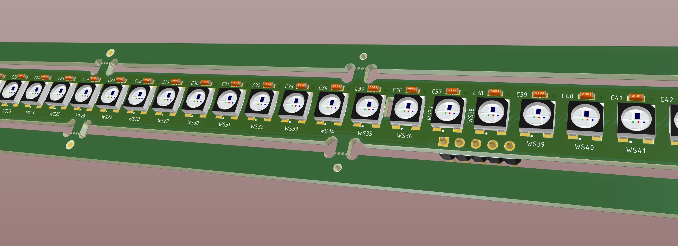
The visualization problem lies in the fact that one must first understand what the light sources will be. I, according to my capabilities, can afford to experiment only on LEDs with built-in drivers. Those. these are the same type of light sources with the same parameters and characteristics for all. Moreover, their location is always fixed, which initially simplified the task. In order to connect this technology to modern fixtures that use the standard DMX interface, I naturally need the help of a company that does this professionally, and for this design option, of course, I need a mechanism for configuring lights.

Now I want to immediately touch on the disadvantages and advantages of this approach.

The advantage is, the types of LEDs I use are widely available, found on PCB assembly lines, and low cost. When ordering the manufacture of printed circuit boards, it is very convenient to order their assembly immediately, which greatly simplifies and reduces the cost of the entire development process.

Disadvantages - These LEDs have a single wire interface and are very slow. Yes, it is faster than DMX, but not fast enough to construct large visualization panels. Secondly, the depth of brightness per color is only 8 bits, which is very, very small for normal color reproduction. Therefore, you have to go to the simplification of the light range. Looking ahead, now there are faster interfaces like SPI for LEDs, with built-in drivers that allow you to work at speeds up to 40 MHz and this is already a solution to the problem of low data transfer rates. And there are already LEDs with 16 bit brightness per color. But here everything starts to rest on the cost of the MCU and the cost of peripherals for data transfer.

I will explain to understand why 16 bits is better than 8 bits of brightness. Imagine that you are in a cinema, the movie starts and the brightness of the lighting decreases and you see that the light is getting dimmer and dimmer and dimmer until it goes out completely. So such lighting on 8-bit LEDs cannot be done. When a command is given to change the brightness from 0 to brightness 1, a huge jump in illumination will be observed. But on 16-bit LEDs, this will be easy. But if for processing 8-bit brightness the computing core can cope with a performance of 5-10Mips, then for 16-bit brightness it is necessary at least 16 times more productive!

I had to make many compromises in development, but the decisive factor was still the option of the minimum cost.

When the visualization data is prepared, they must be sent to the output optical device (OOD), for this a mechanism was invented, called visualization matrices, the main task of which is to control the symmetry and diversity of the images created.

The overall dimensions of the prototypes for the M68 and M100 were due to the technical capabilities of the printed circuit board manufacturers and customs restrictions, which allow the introduction of goods without additional taxation up to a certain value. That is, the fewer printed circuit boards in the device, the cheaper it is. The number of printed circuit boards that contain devices for M68 is two printed circuit boards, for M100 - one printed circuit board, LEDs with side glow were used in it.

Functionally, projects like CLUBBEST look like this:

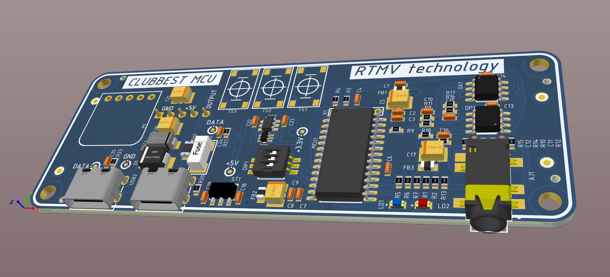
Technically, everything is very simple. All the main work is done by the microcontroller.

Where did the numbers 68 or 100 come from - this is the number of light sources used in the project.

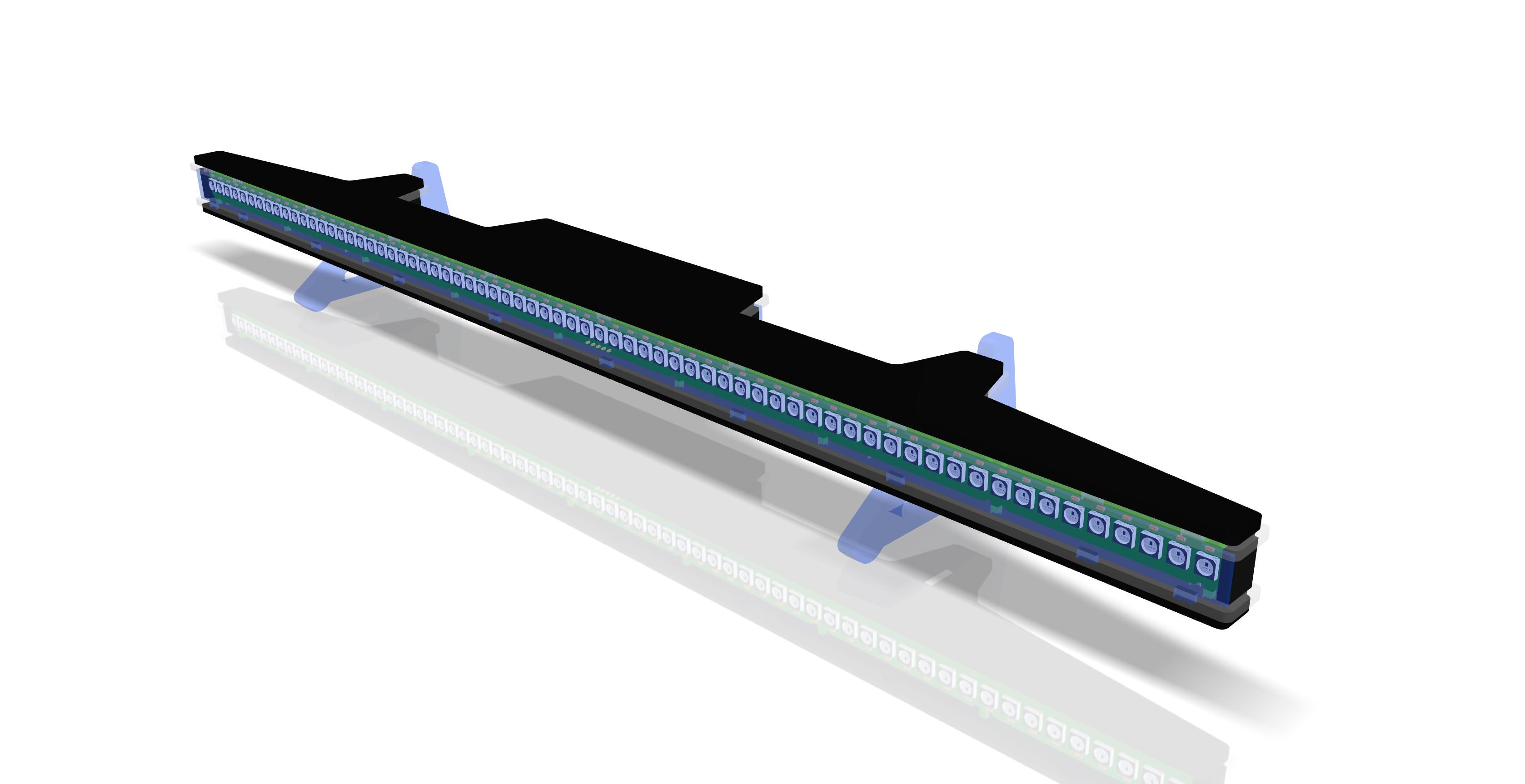
Circuitry and PCB design is one side of the issue, the other is case design. The project itself was implemented two years ago, at that time printing 3D cases even of this size was problematic, but today in China there are a sufficient number of factories performing 3D printing, and the price of 3D printing has dropped significantly, so I think to implement new options for the case with 3D printing.

The cases for CLUBBEST were made of laser-cut acrylic. There were many options, but the final one was this.

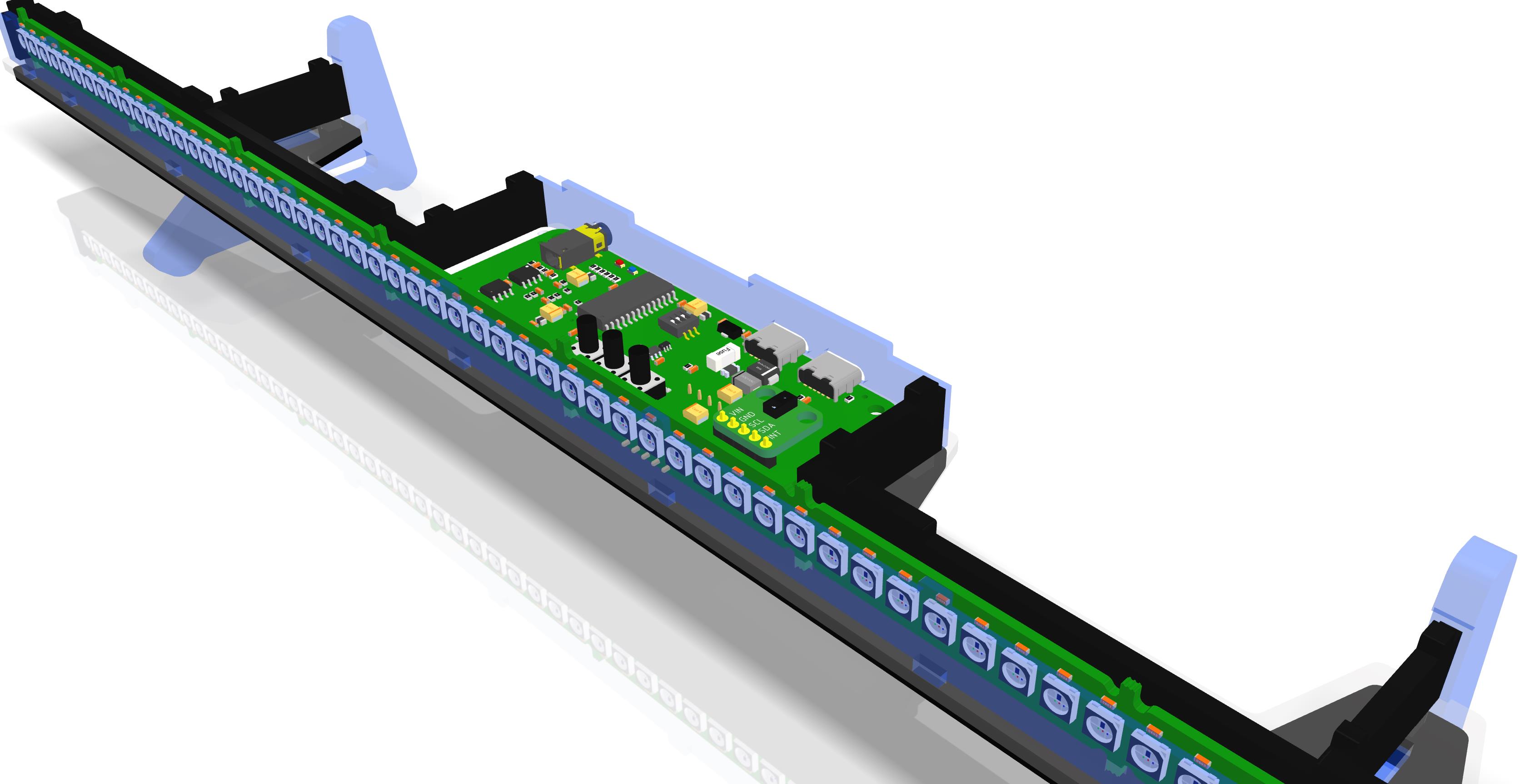
in the case, one printed circuit board is the processor for processing and converting the sound stream itself, and the second is the LED display.

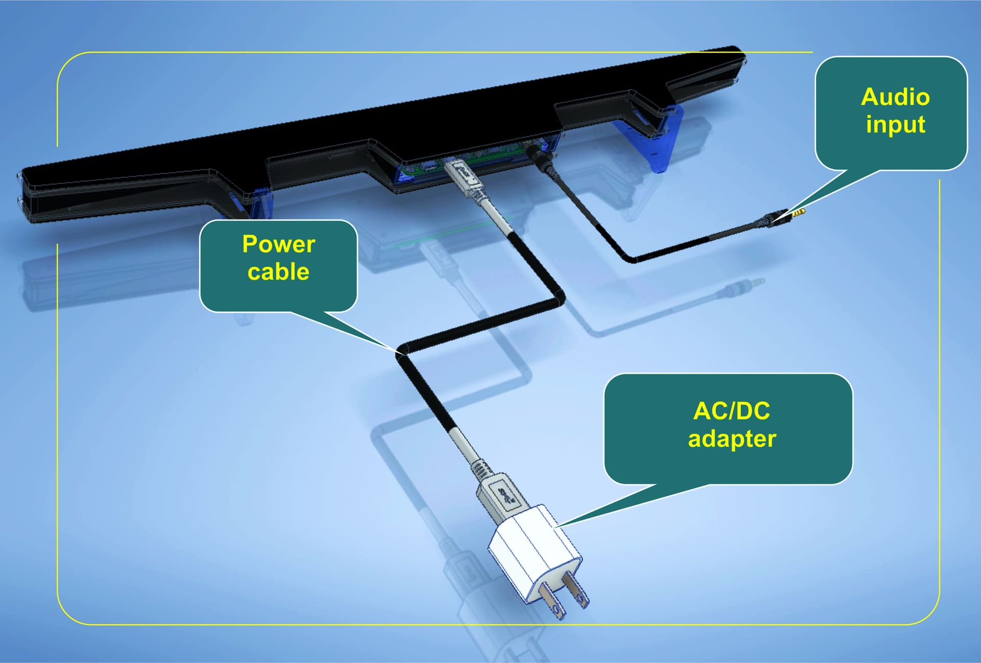
For audio input, a 3.5mm audio connector is used, power is supplied via USB Type-C, the second USB connector is for connecting a repeater. The repeater has exactly the same appearance as the main unit, but it only has an adapter board and an LED board.

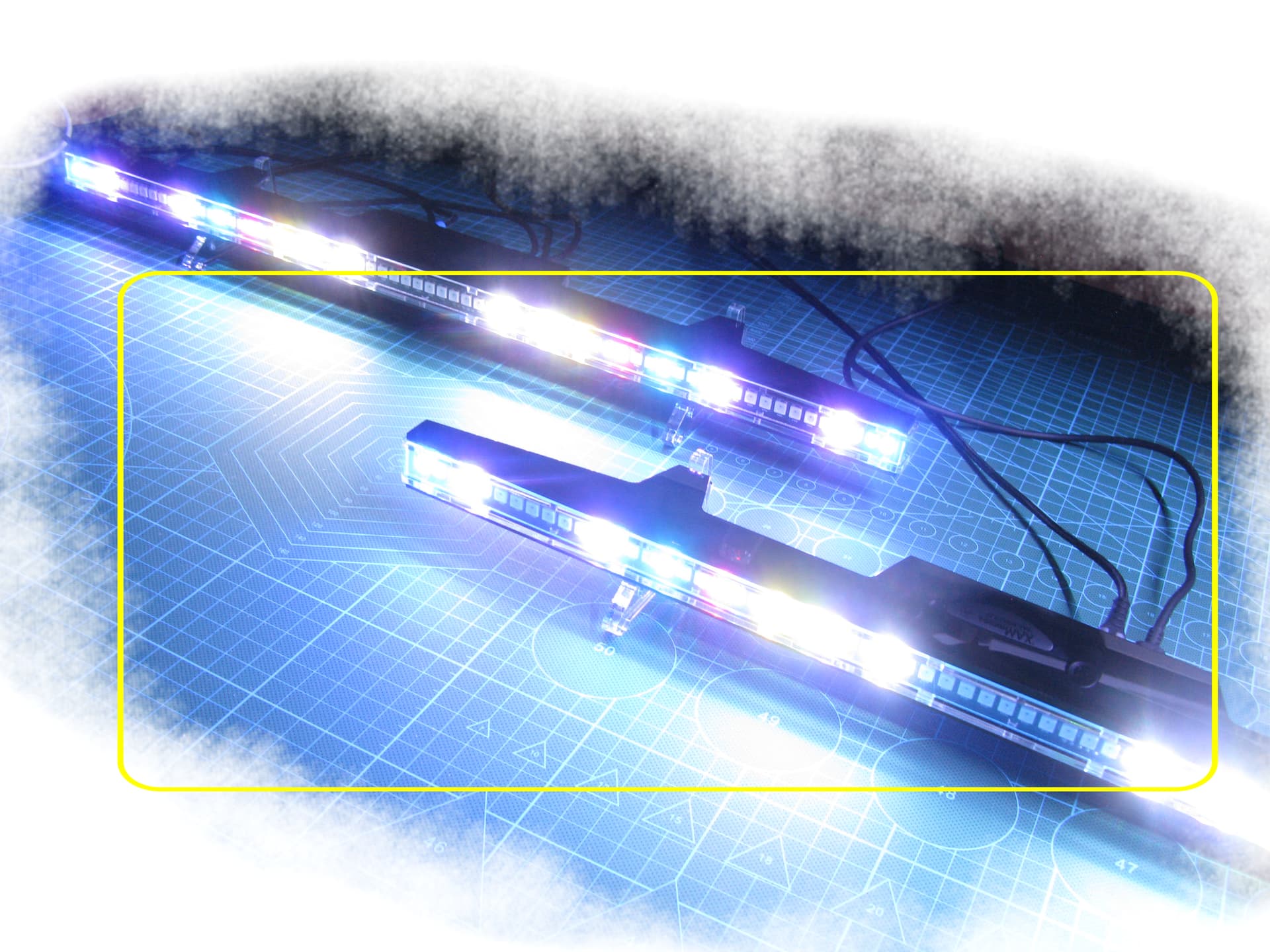
This is what the real connection looks like, audio and power cable, for CLUBBEST M 68. I think that the solution turned out to be as simple and convenient as possible.

Here you can download a 3D-pdf in which you can independently examine and disassemble the CLUBBEST M68 case into spare parts. sborka_v6-osnovnoju2.pdf (2.0 MB)

To be continued…

And this is another video…

Agreed. I get the impression that this person is only here to advertise.

1 Like

Yeah, I’m tempted to close this topic as well.

1 Like

It’s another case where the forums anti-bump feature (a member replying to their own post) should be re-enabled.

1 Like

No problem, close the topic, my goal was to explain in more detail the technology that I propose, but I understand that there are ambitions that are difficult to overcome. If anyone would like to develop this project with me, you know how to contact me.

I would, like staff above mentioned, start a blog so those interested can follow your progress. Seems that there’s not much response here. Most already use a lighting system.

@Catcatcat Just came across this and its defiantly peaked my interest. I happen to currently utilize 2 artnet matrice, each consisting of 1050 RGBW pixels each, covering the 2 opposing walls on either side of the booth in the little home studio space I built to keep busy throughout the pandemic.

Currently I’m able to feed the array from Resolume Arena via a custom mapped “DMX lumiverse” I created within the program (however this obviously is less than ideal if im Spinning without a VJ on site with me to actually operate Resolume (as the program’s built in automation functions are relatively limited in scope)

of course, technically I can really feed it source material from anywhere but considering the relatively low pixel density, and suboptimal refresh rate (~20fps) pushing content not specifically rendered with these traits in mind tend too produce suboptimal results.

Would love to chat and find out if you’ve had any progress with the project since your last post!

Cheers!

I have postponed this project for today, this is due to problems and customs restrictions when supplying electronics to a combat zone (Ukraine). Today there are problems with the order and their production of printed circuit boards and the purchase of components. Although I had the feeling that today there is no need for such a direction of visualization.