Good afternoon. I have a system consisting of two SC6000s, two LC6000s and an X1850 mixer. I have them connected from left to right as follows: LC6000, SC6000, X1850, SC6000, LC6000. How should the connections be made so that the first LC6000 that controls layer B of the first SC6000 is on channel 1, the first SC6000 (layer A) is on channel 2, the second SC6000 (layer A) is on channel 3 and the last LC6000 is on channel 4?
Surely by reading the manual of the x1850 and the LC6000’s you can figure it out.
Thanks, but I don’t think the LC6000s will have much impact in this case
Aren’t there diagrams in the SC6000 and X1850 manuals?
I’ve got this set up at home. I’ll take a pic for you tomorrow when I’m back if you’re a still struggling fella ![]()
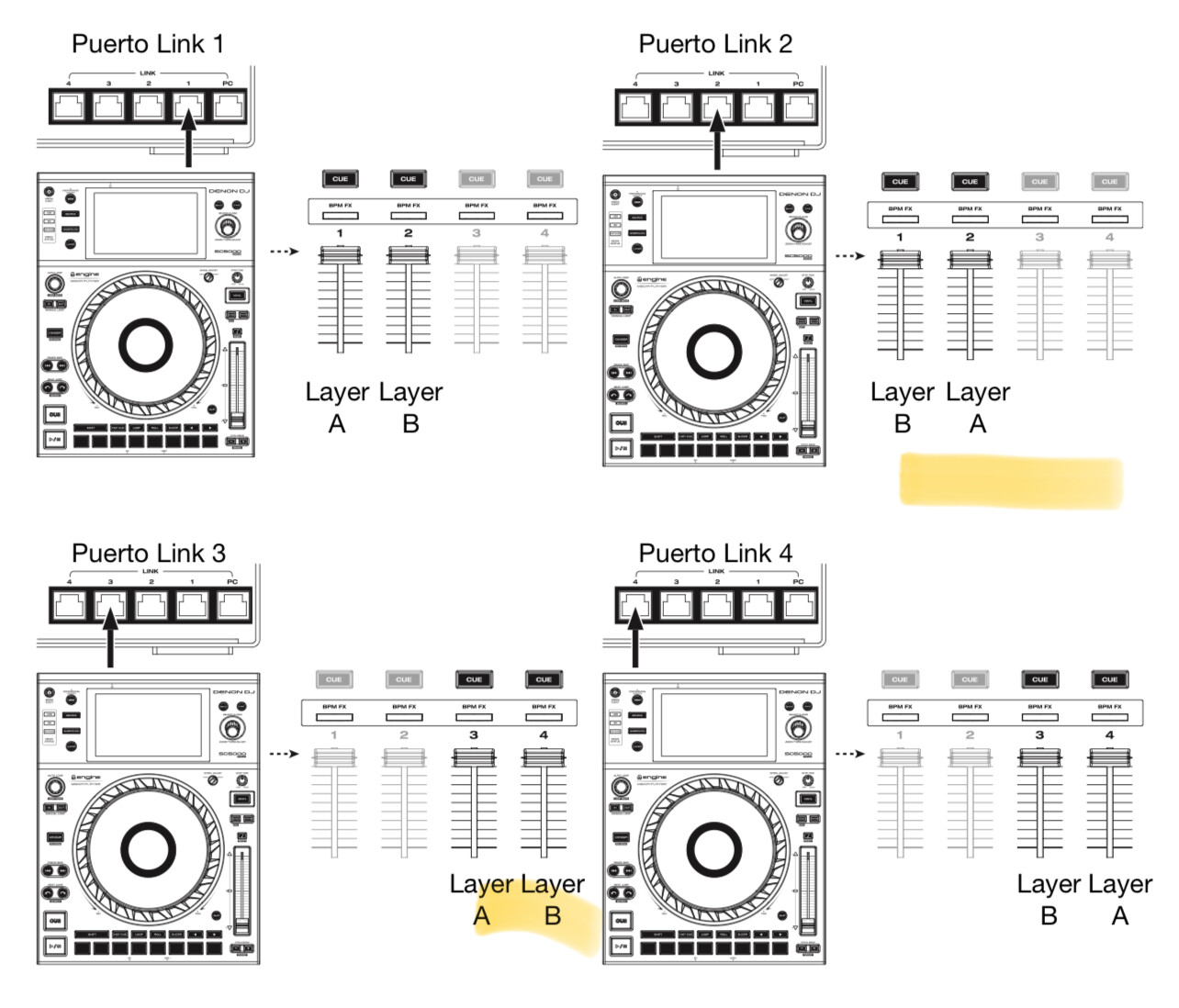
Just connect the ethernet to the port number, where you’d want layer A of that device to be.
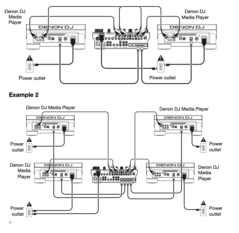
I have already given the configuration, the left SC6000, the RCA of layer B to channel 1 and layer A to channel 2 and connected to the link 2 port of the X1850, and the right SC6000, RCA of layer A to channel 3, layer B to channel 4 and connected to the link 3 port of the X1850
I know, but as you don’t want to read manuals, just remember my simple “rule of thumb”. ![]()
On X1850 CH 1 -Layer B (LC 6000 left) , CH 2- Layer A (SC6000 left), CH 3 - Layer A (SC6000 right), CH 4 - Layer B (LC 6000 right). Use RCA output on the mixer accordingly. You can connect SC6000 via USB or ethernet in the back of the mixer. Audio for LC6000, you need to use SC6000 1&4 RCA output in channel 1&4 0n X1850.